
Systems and methods for detecting leakage currents in high-frequency ablation systems

a leakage current and high-frequency ablation technology, applied in the field of high-frequency ablation systems, can solve the problems of destroying biological tissue, causing damage to the patient's body, and causing damage to the patient's body, and conventional techniques for addressing leakage current in rf ablation systems are less than optimal and have significant drawbacks

Pending Publication Date: 2022-06-16
ADVANCED NEUROMODULATION SYST INC
View PDF0 Cites 0 Cited by
  • Summary
  • Abstract
  • Description
  • Claims
  • Application Information

AI Technical Summary

Benefits of technology

This patent is about a system and method for detecting and addressing leakage currents in RF ablation systems. The system can control switches to aid in detecting leakage currents and can regulate RF power to control or abort the ablation therapy if there is a lot of leakage. The technical effect of this patent is that it allows for the detection and addressing of leakage currents without having to redesign the hardware of the RF ablation system.

Problems solved by technology

Typically, RF ablation causes the destruction and / or removal of biological tissue.
Due to non-ideal conditions in RF ablation systems, not all of the electrical current from an RF generator will likely flow from the active electrode to the neutral electrode.
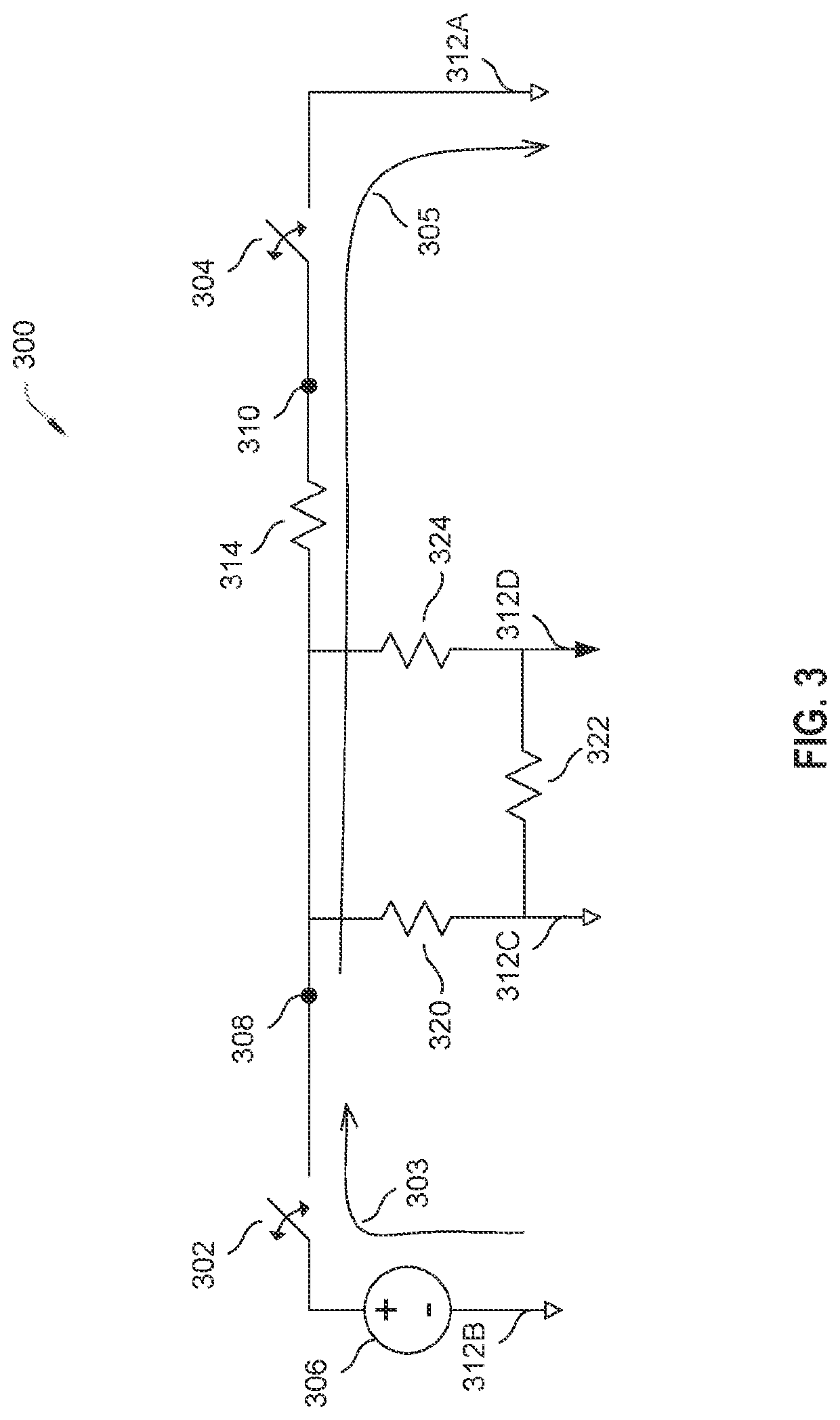
For example, due to at least the electrical network presented by the patient, poor isolation of the patient from ground (earth), and parasitics associated with an RF ablation system, a leakage current path can be created.
Conventional techniques for addressing leakage current in RF ablation systems are less than optimal and have significant drawbacks.
For example, simulation tools tend to be inaccurate at high-frequency operating conditions and for very complex hardware systems, making them unreliable for accurate simulation of RF ablation systems.

Method used


Image

  • Systems and methods for detecting leakage currents in high-frequency ablation systems
  • Systems and methods for detecting leakage currents in high-frequency ablation systems
  • Systems and methods for detecting leakage currents in high-frequency ablation systems

Examples


Embodiment Construction

[0018]The detailed description set forth below, in connection with the appended drawings, is intended as a description of various configurations and is not intended to limit the scope of the disclosure. Rather, the detailed description includes specific details for the purpose of providing a thorough understanding of the inventive subject matter. It will be apparent to those skilled in the art that these specific details are not required in every case and that, in some instances, well-known structures and components are shown in block diagram form for clarity of presentation.

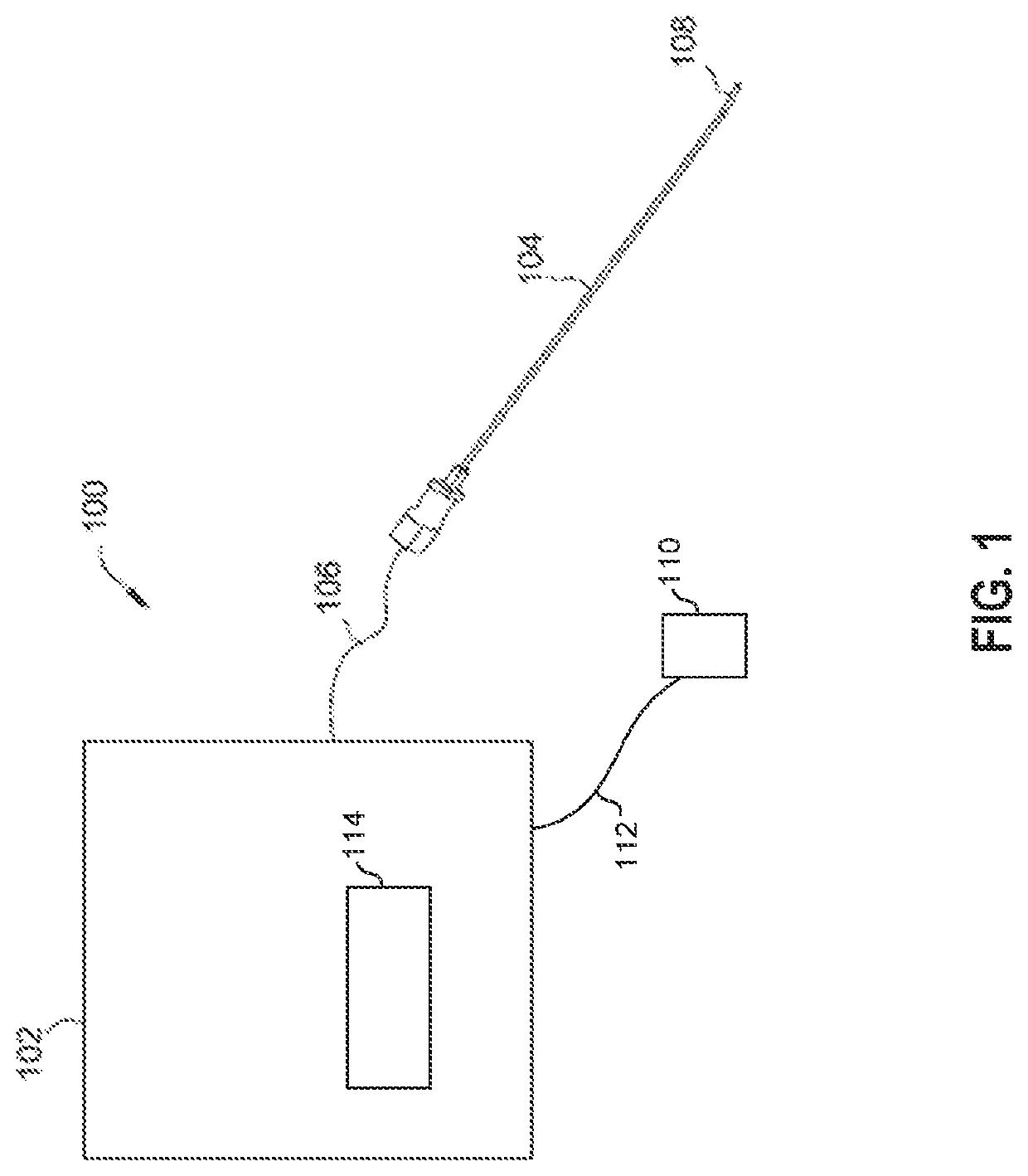
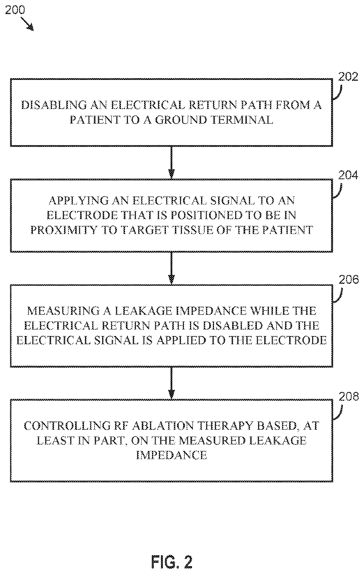
[0019]The present disclosure provides systems and methods for detecting leakage currents in radio-frequency (RF) ablation systems and for allowing the detected leakage currents to be addressed without complete redesign of the hardware of the RF ablation systems. In some embodiments, an RF ablation system may control switches within the RF ablation system to aid the detection of leakage currents. According to som...


PUM


Abstract

The present disclosure provides systems and methods for detecting leakage currents in radio-frequency (RF) ablation systems. An RF generator may be configured to disable an electrical return path from a patient to a ground terminal. The RF generator may also be configured to apply an electrical signal to an electrode that is positioned to be in proximity to target tissue of the patient. The RF generator may be further configured to measure a leakage impedance while the electrical return path is disabled and the electrical signal is applied to the electrode. The RF generator may also be configured to control RF ablation therapy based, at least in part, on the measured leakage impedance. Other features are also claimed and described.

Description

CROSS-REFERENCE TO RELATED APPLICATIONS[0001]The present application claims the benefit of U.S. Provisional Application No. 63 / 126,288, filed Dec. 16, 2020 and entitled “SYSTEMS AND METHODS FOR DETECTING LEAKAGE CURRENTS IN HIGH-FREQUENCY ABLATION SYSTEMS,” the disclosure of which is incorporated by reference herein in its entirety.FIELD OF THE DISCLOSURE[0002]The present disclosure relates generally to high-frequency ablation systems, and more particularly to techniques for detecting leakage currents in radio-frequency (RF) ablation systems. Certain aspects of the technology discussed below can enable and provide enhanced features and techniques for RF ablation systems, including better patient safety, better RF power delivery, and lower cost.BACKGROUND OF THE DISCLOSURE[0003]RF ablation may be used to treat numerous health conditions. For example, RF ablation may be used to treat tumors, arrhythmia, skin conditions, and chronic pain.[0004]Typically, RF ablation causes the destruct...

Claims


Application Information

Patent Timeline
IPC IPC(8): A61B18/16A61B18/12
CPCA61B18/16A61B2018/00577A61B18/1206A61B18/1233A61B2018/00875A61B2018/00666A61B2018/00678A61B2018/1253
Inventor OH, SEILBALASINGH, BINESHWINSTROM, WILLIAMSINGH, SIMRAN
Owner ADVANCED NEUROMODULATION SYST INC
Learn More