Apparatus and method for evaluating knee geometry

a knee and geometry technology, applied in the field of knee geometry apparatus and methods, can solve the problems of inability difficulty and complex to achieve proper balance, and state-of-the-art gap balancing devices cannot enable balancing

Pending Publication Date: 2022-06-16
LITTLE ENGINE LLC
View PDF0 Cites 0 Cited by
  • Summary
  • Abstract
  • Description
  • Claims
  • Application Information

AI Technical Summary

Problems solved by technology

One problem with prior art balancing techniques is that it is difficult and complex to achieve the proper balance.
Current state-of-the-art gap balancing devices do not enable balancing with the patella in-place and are large, overly-complicated devices that work only with their respective knee systems They also cannot measure ligament tension throughout the range of knee motion.

Method used


Image

  • Apparatus and method for evaluating knee geometry
  • Apparatus and method for evaluating knee geometry
  • Apparatus and method for evaluating knee geometry

Examples


Embodiment Construction

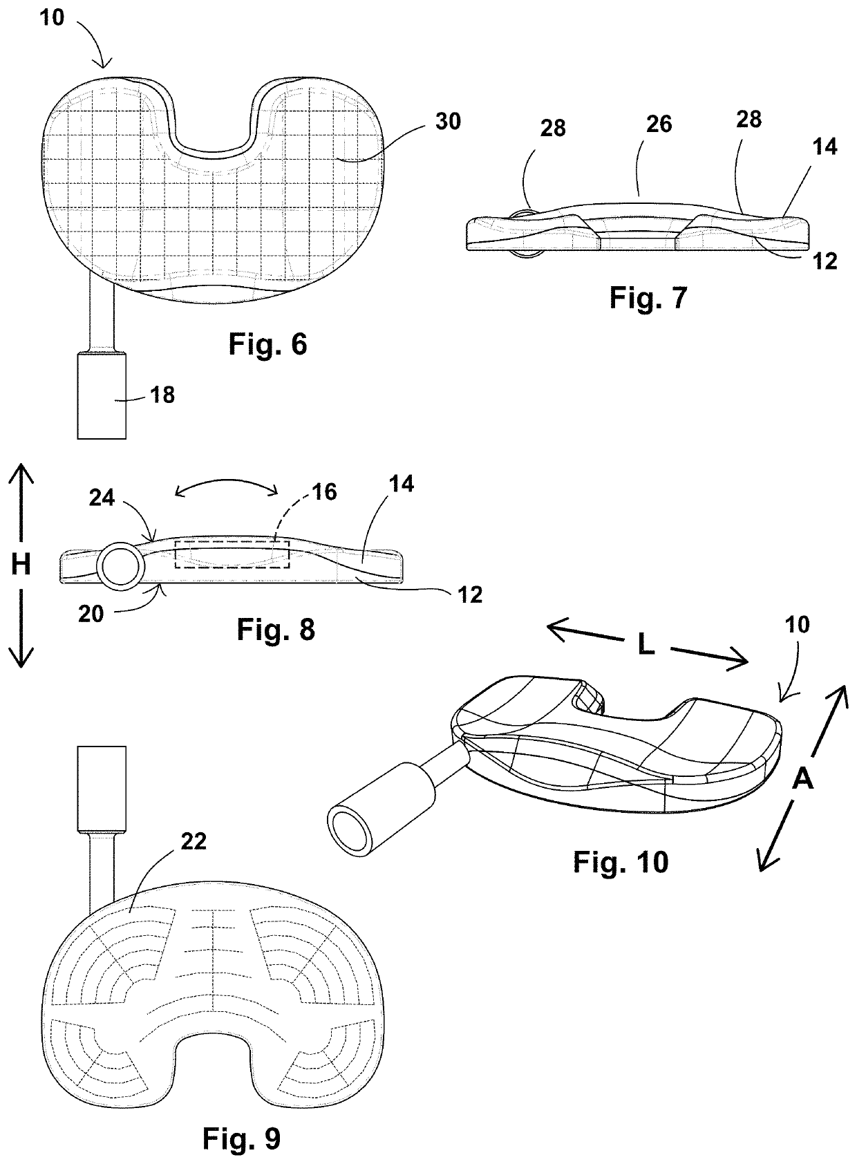
[0069]Now, referring to the drawings wherein identical reference numerals denote the same elements throughout the various views, FIGS. 6-10 depict an exemplary embodiment of a gap balancer 10 (alternatively referred to in various embodiments as a tensioner-balancer, distractor, distractor-tensioner, or jack) which is useful for balancing a gap in a human knee joint as part of a total knee arthroscopy and for other therapeutic procedures.

[0070]The gap balancer 10 comprises a baseplate 12 and a top plate 14 interconnected by a distractor element 16 (shown schematically). The distractor element 16 and the gap balancer 10 are movable between a retracted position in which the top plate 14 lies close to or against the baseplate 12, and an extended position in which the top plate 14 is spaced away from the baseplate 12. As described in more detail below, a means is provided to actuate the distractor element 16 in response to an actuating force in order to separate the baseplate 12 and the ...


PUM

PropertyMeasurementUnit
gap heightaaaaaaaaaa
heightaaaaaaaaaa
thicknessaaaaaaaaaa

Abstract

A method of evaluating a human knee joint which includes a femur bone, a tibia bone, a patella bone, a patellar tendon, and ligaments, wherein the ligaments and patellar tendon are under anatomical tension to connect the femur and tibia together, creating a load-bearing articulating joint, the method including: inserting into the knee joint a gap balancer that includes a tibial interface surface, an opposed femoral interface surface, and at least one force sensor, the method including: providing an electronic receiving device; moving the knee joint through at least a portion of its range of motion; while moving the knee joint, using the electronic receiving device to collect data from the at least one force sensor; processing the collected data to produce a digital geometric model of at least a portion of the knee joint; and storing the digital geometric model for further use.

Description

BACKGROUND[0001]This invention relates generally to medical devices and instruments, and more particularly to a method for evaluating the geometry of a human knee joint in order to facilitate repair, augment, or replacement.[0002]Total knee arthroplasty (“TKA”) is a procedure for treating an injured, diseased, or worn human knee joint. In a TKA, an endoprosthetic joint is implanted, replacing the bearing surfaces of the joint with artificial members. Proper alignment of the joint and substantially equal tension in the soft tissues surrounding the joint are important factors in producing a good surgical outcome.[0003]A human knee joint “J” is shown in FIGS. 1-4. The joint J is prepared for implantation by cutting away portions of the femur “F” and the tibia “T”. FIGS. 1 and 2 show the joint in extension, with cutting planes for a tibial cut 1 and a distal femoral cut 2. The tibial cut 1 and the distal femoral cut 2 cooperate to define an extension gap “EG”. FIGS. 3 and 4 show the joi...

Claims


Application Information

Patent Timeline
Patent Type & Authority Applications(United States)
IPC IPC(8): A61F2/46G16H50/20A61B34/20G16H20/40A61B5/00G16H40/67G16H40/20G01L5/16A61B34/10G16H10/60
CPCA61F2/4657G16H50/20A61B34/20A61F2/461G16H20/40A61B5/4585A61B2034/256G16H40/20G01L5/16A61B34/10A61B5/4533G16H10/60G16H40/67A61F2002/4666A61F2002/3895A61B5/1036A61B5/686A61B17/1622A61B2017/0268A61B17/025A61B2090/065A61B17/14A61B2034/2055A61B2090/502A61B2017/00557A61B2017/00398A61B2034/105A61B2090/064A61B2090/3983A61B5/6847A61F2002/4633
Inventor COLE, J. DEANKELLAR, FRANZ W.BISSETTE, MICHAEL D.KELLAR, FRANZ AUSTENCROWDER, HAROLD L.
Owner LITTLE ENGINE LLC
Why Eureka
Try Eureka