
Optical lens assembly, imaging apparatus and electronic device

a technology of optical lens and optical lens element, applied in the field of optical lens assembly and imaging apparatus, can solve the problems of large increase in the surface shape of the optical lens element adjacent to the image surface, and achieve the effect of improving the optical lens element surface shape and improving the optical lens

Pending Publication Date: 2022-06-23
LARGAN PRECISION
View PDF0 Cites 0 Cited by
  • Summary
  • Abstract
  • Description
  • Claims
  • Application Information

AI Technical Summary

Benefits of technology

The present disclosure describes an optical lens assembly with several optical lens elements. The assembly uses atomic layer deposit coating to create a high-quality coating with specific anti-reflective factors. This design ensures that the assembly has excellent image quality and solves the problem of strong light reflecting from the lens elements. The technique helps create a uniform coating across the entire field of view of the curved lens element, resulting in improved image quality for the optical lens assembly. This technique is advantageous for high-end optical lens assemblies as it enhances image quality.

Problems solved by technology

Due to the growing difficulty in designing the optical systems and the increment of lens elements, the changes of surface shape of the optical lens element adjacent to the image surface greatly increase because the huge aberration of off-axis field need to be corrected, which becomes a bottleneck that cannot be overcome in the conventional coating techniques.

Method used


Image

  • Optical lens assembly, imaging apparatus and electronic device
  • Optical lens assembly, imaging apparatus and electronic device
  • Optical lens assembly, imaging apparatus and electronic device

Examples


1st embodiment

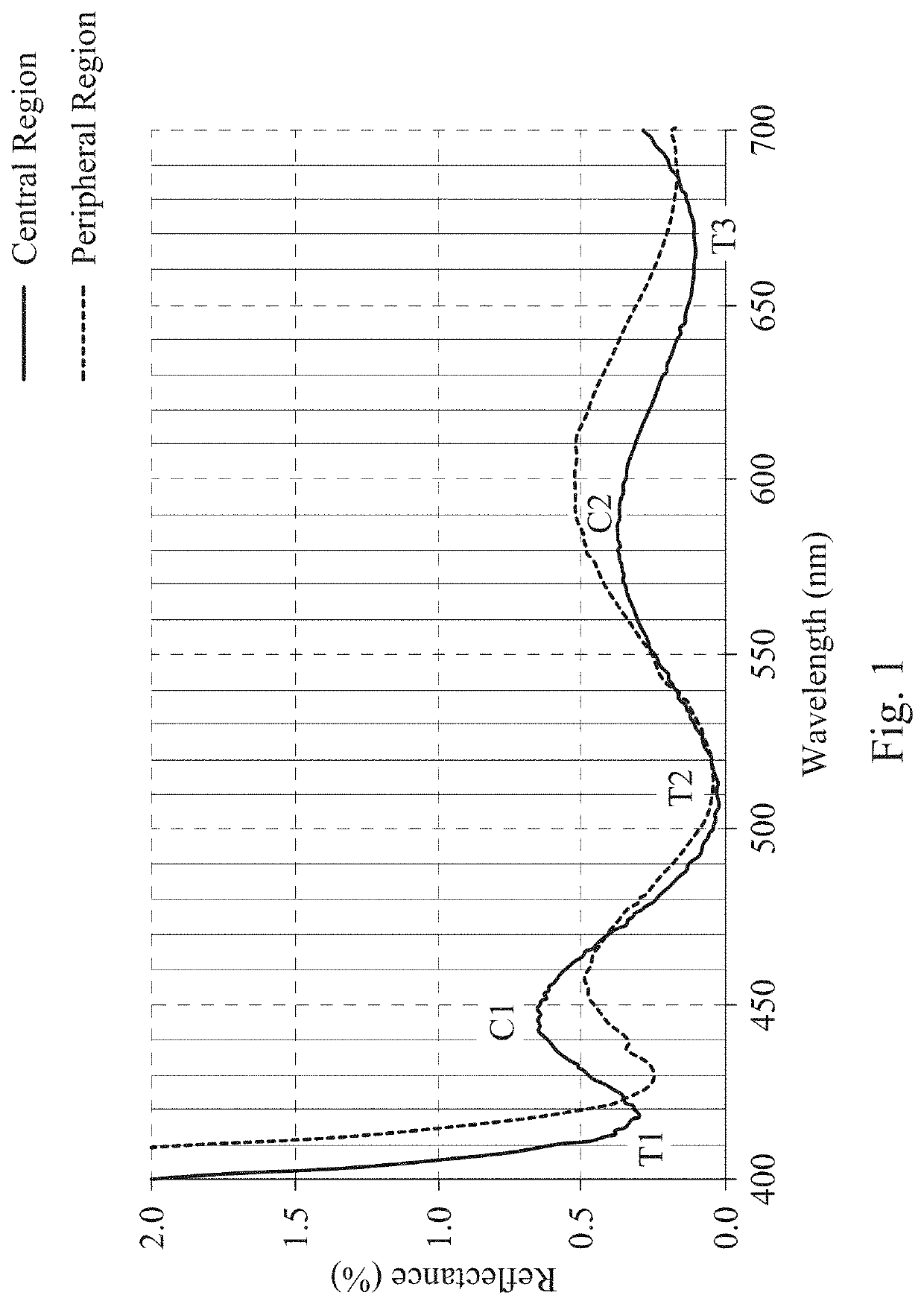
[0108]The optical lens assembly according to the 1st embodiment includes four optical lens elements, which are, from an object side to an image side, an optical lens element L1, an optical lens element L2, an optical lens element L3 and an optical lens element L4. At least one of the four optical lens elements includes an anti-reflective coating. The at least one optical lens element including the anti-reflective coating is made of a plastic material. The anti-reflective coating is arranged on an object-side surface or an image-side surface of the at least one optical lens element including the anti-reflective coating. The anti-reflective coating includes at least one coating layer. One of the at least one coating layer at the outer of the anti-reflective coating is made of ceramics. The anti-reflective coating includes a plurality of holes, and sizes of the plurality of holes adjacent to the outer of the anti-reflective coating are larger than sizes of the plurality of holes adjace...

2nd embodiment

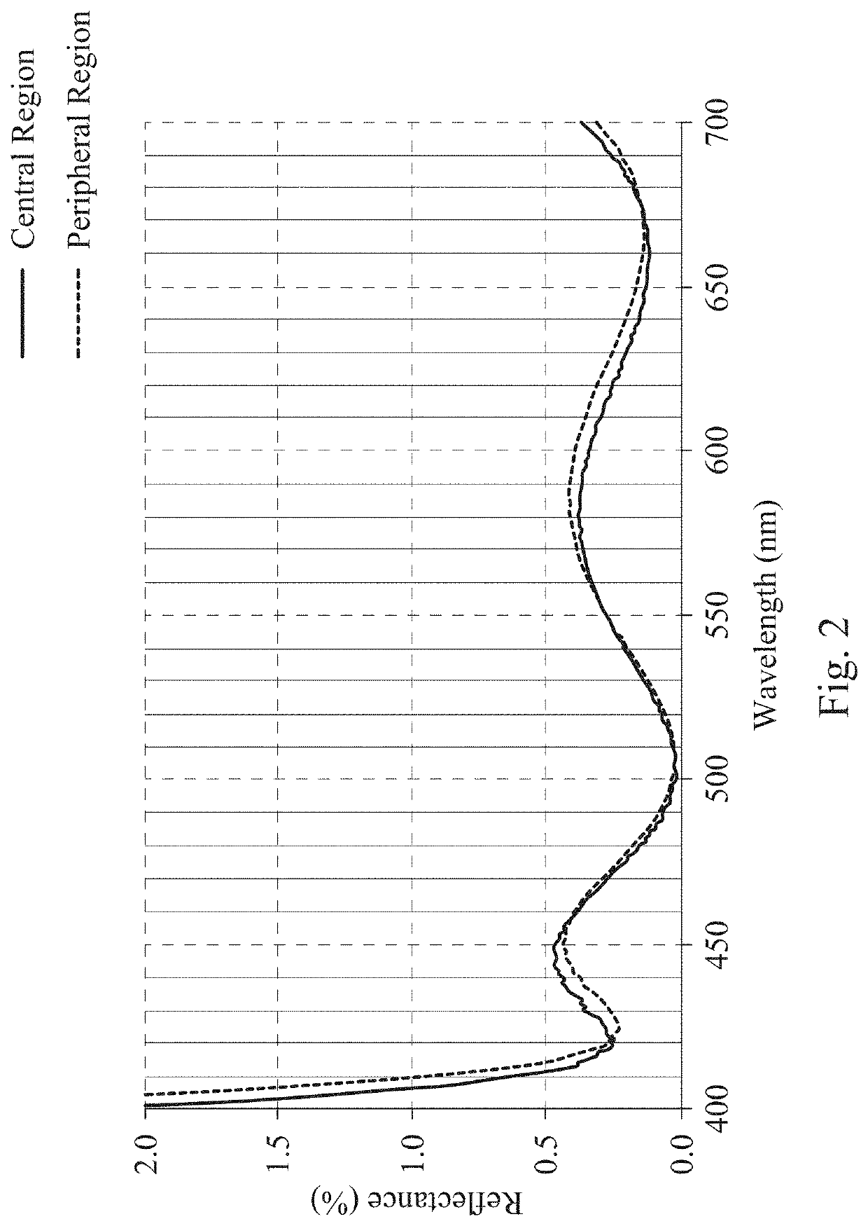
[0123]The optical lens assembly according to the 2nd embodiment includes five optical lens elements, which are, from an object side to an image side, an optical lens element L1, an optical lens element L2, an optical lens element L3, an optical lens element L4 and an optical lens element L5. At least one of the five optical lens elements includes an anti-reflective coating. The at least one optical lens element including the anti-reflective coating is made of a plastic material. The anti-reflective coating is arranged on an object-side surface or an image-side surface of the at least one optical lens element including the anti-reflective coating. The anti-reflective coating includes at least one coating layer. One of the at least one coating layer at the outer of the anti-reflective coating is made of ceramics. The anti-reflective coating includes a plurality of holes, and sizes of the plurality of holes adjacent to the outer of the anti-reflective coating are larger than sizes of t...

3rd embodiment

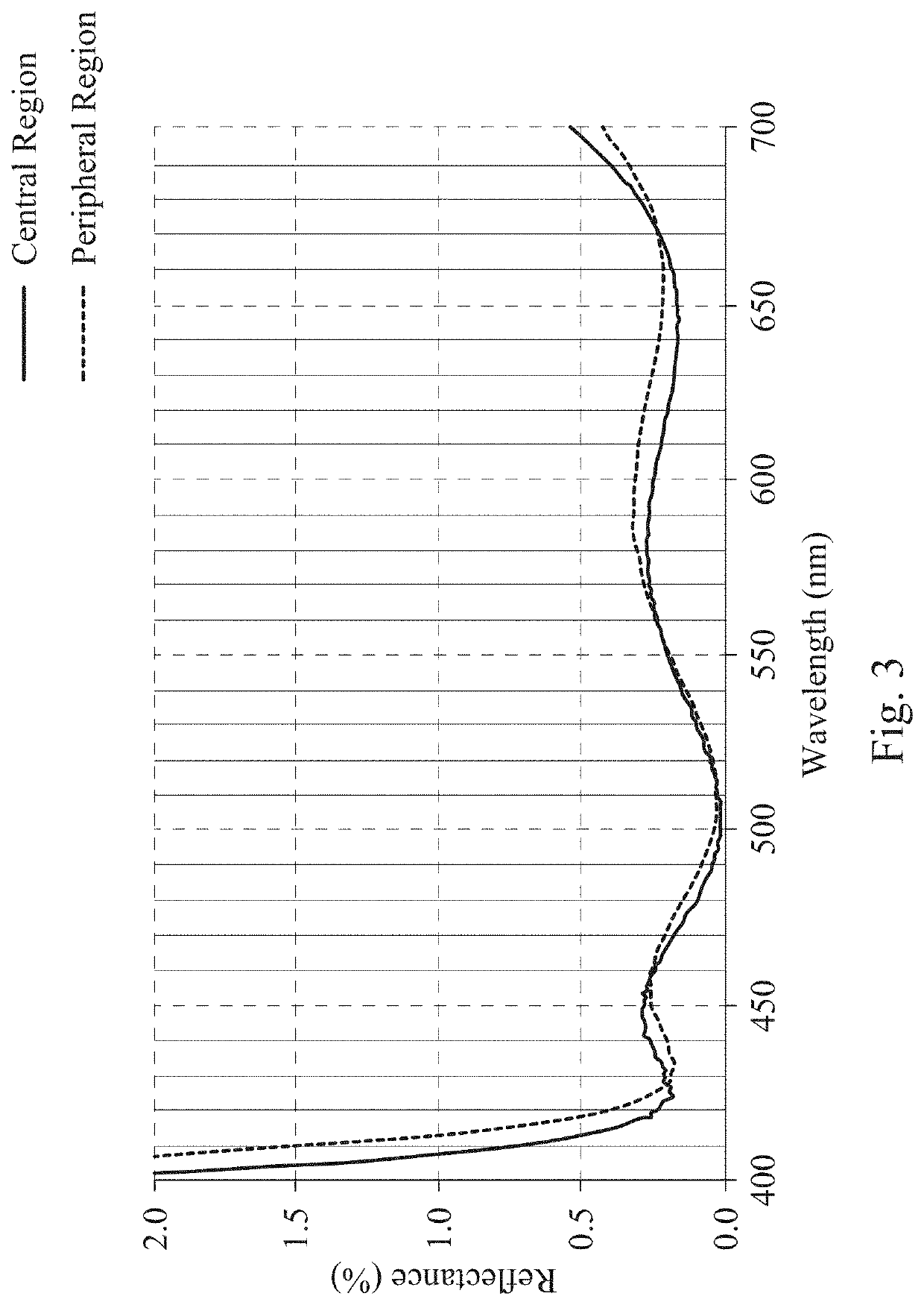
[0125]The optical lens assembly according to the 3rd embodiment includes five optical lens elements, which are, from an object side to an image side, an optical lens element L1, an optical lens element L2, an optical lens element L3, an optical lens element L4 and an optical lens element L5. At least one of the five optical lens elements includes an anti-reflective coating. The at least one optical lens element including the anti-reflective coating is made of a plastic material. The anti-reflective coating is arranged on an object-side surface or an image-side surface of the at least one optical lens element including the anti-reflective coating. The anti-reflective coating includes at least one coating layer. One of the at least one coating layer at the outer of the anti-reflective coating is made of ceramics. The anti-reflective coating includes a plurality of holes, and sizes of the plurality of holes adjacent to the outer of the anti-reflective coating are larger than sizes of t...


PUM


Abstract

An optical lens assembly includes, from an object side to an image side, at least four optical lens elements. At least one of the at least four optical lens elements includes an anti-reflective coating. The at least one optical lens element including the anti-reflective coating is made of a plastic material. The anti-reflective coating is arranged on an object-side surface or an image-side surface of the at least one optical lens element including the anti-reflective coating. The anti-reflective coating includes at least one coating layer. One of the at least one coating layer at the outer of the anti-reflective coating is made of ceramics. The anti-reflective coating includes a plurality of holes, and sizes of the plurality of holes adjacent to the outer of the anti-reflective coating are larger than sizes of the plurality of holes adjacent to the inner of the anti-reflective coating.

Description

RELATED APPLICATIONS[0001]This application claims priority to U.S. Provisional Application Ser. No. 63 / 129,826, filed Dec. 23, 2020, U.S. Provisional Application Ser. No. 63 / 137,772, filed Jan. 15, 2021, and Taiwan Application Serial Number 110121227, filed Jun. 10, 2021, which are herein incorporated by reference.BACKGROUNDTechnical Field[0002]The present disclosure relates to an optical lens assembly and an imaging apparatus. More particularly, the present disclosure relates to an optical lens assembly and an imaging apparatus for preventing reflection.Description of Related Art[0003]A usable anti-reflective coating only can be manufactured on a planar surface by the conventional coating techniques (PVD and general CVD). In high-end mobile devices, the requirements of lens assemblies with high quality significantly increase, and the number of lens elements in the high-end lens assemblies also significantly increases correspondingly. Due to the growing difficulty in designing the o...

Claims


Application Information

Patent Timeline
IPC IPC(8): G02B1/115
CPCG02B1/115G02B3/08G02B13/0015G02B1/118G02B9/34G02B13/004G02B27/0012G02B1/002G02B13/18
Inventor TSAI, WEN-YUCHANG, CHIEN-PANGCHI, CHI-WEIHONG, WEI-FONGTENG, CHUN-HUNGCHU, KUO-CHIANG
Owner LARGAN PRECISION
Learn More