Communication control system, communication control method, communication control apparatus and communication control program

Pending Publication Date: 2022-06-23
NIPPON TELEGRAPH & TELEPHONE CORP
View PDF0 Cites 0 Cited by
  • Summary
  • Abstract
  • Description
  • Claims
  • Application Information

AI Technical Summary

Benefits of technology

[0030]According to the present invention, it is possible to prevent resources for the queue length and shaping rate of the SWs from being over allocate

Problems solved by technology

However, since it is difficult to know in advance which SW the microburst originates from, it is necessary for ea

Method used


Image

  • Communication control system, communication control method, communication control apparatus and communication control program
  • Communication control system, communication control method, communication control apparatus and communication control program
  • Communication control system, communication control method, communication control apparatus and communication control program

Examples


first embodiment

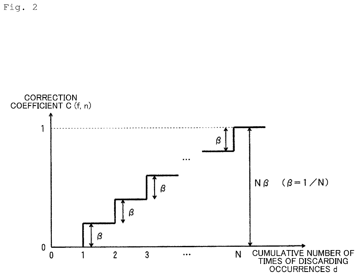
[0044]FIG. 2 illustrates an outline of updating the correction coefficient C(f, n) in a first embodiment.

[0045]In FIG. 2, the horizontal axis represents the cumulative number of times of discarding occurrences d, which is the cumulative number of times the amount of discarded data collected for the flow ID: f from SW #n was not 0. The vertical axis is the correction coefficient C(f, n) collected for the flow ID: f from SW #n, where the correction coefficient is β for a cumulative number of times of discarding occurrences d of 1 and increases by 3 each time the cumulative number of times of discarding occurrences d increases by 1, and its upper limit is 1. Accordingly, the correction coefficient C(f, n) is given by the following equation.

C(f,n)=min(1,d×β)

[0046]Here, β is a predetermined value, and for example, in a case where the cumulative number of times of discarding occurrences when the correction coefficient C(f, n) reaches the upper limit of 1 is set to N, it is represented as

β...

second embodiment

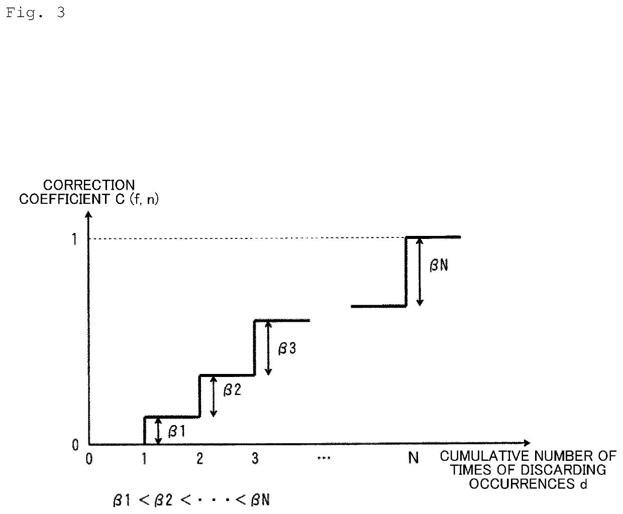
[0049]FIG. 3 illustrates an outline of updating the correction coefficient C(f, n) in a second embodiment.

[0050]In FIG. 3, the horizontal axis represents the cumulative number of times of discarding occurrences d. The vertical axis is the correction coefficient C(f, n) collected for the flow ID: f from SW #n, and the correction coefficient increases by βd according to the cumulative number of times of discarding occurrences d. Accordingly, the correction coefficient C(f, n) is set as

β1,β2, . . . ,β(N−1),βN

according to the cumulative number of times of discarding occurrences d. Here, N is the cumulative number of times of discarding occurrences when the correction coefficient C(f, n) reaches 1, and

β1,β2, . . . ,β(N−1)N

may be set so that the rate of increase in the correction coefficient C(f, n) increases as the cumulative number of times of discarding occurrences d increases. Or

β1,β2, . . . ,β(N−1)>βN

may be set so that the rate of increase in the correction coefficient C(f, n) dec...

third embodiment

[0051]FIG. 4 illustrates an outline of updating the correction coefficient C(f, n) in a third embodiment.

[0052]In FIG. 4, the horizontal axis represents the cumulative number of times of discarding occurrences d. The vertical axis is the correction coefficient C(f, n) collected for the flow ID: f from SW #n, where the correction coefficient is α for a cumulative number of times of discarding occurrences d of 1 and increases by β each time the cumulative number of times of discarding occurrences d increases by 1. Accordingly, the correction coefficient C(f, n) is given by the following equation.

d=1:C(f,n)=α

d≥2:C(f,n)=min(1,α+d×β)

[0053]Here, α and β are both predetermined values, and for example, are represented as

α=δ / γ

β=(1−α) / (N−1)

where γ [s] is a collection time interval of the amount of discarded data, δ [s] is an average length of microbursts, and N is the cumulative number of times of discarding occurrences when the correction coefficient C(f, n) reaches the upper limit of 1. In ...


PUM


Abstract

A communication control system includes a plurality of layer 2 switches (SWs); and a communication control device that controls communication of the SWs. Each SW includes one or more queues that each have a variable queue length for accumulating input frames, and a transmission unit that has a shaping function of transmitting the frames accumulated in the queues to a desired destination at a desired rate. The communication control device includes a correction processing unit that acquires an amount of discarded data generated in each queue of the SW, and multiplies the acquired amount of discarded data by a correction coefficient weighted by the cumulative number of times of discarding occurrences for which the amount of discarded data is not 0 to obtain a corrected amount of discarded data; and an adjustment processing unit that determines adjustment values for the queue length of each queue and shaping rate of the SW based on the corrected amount of discarded data, and notifies each SW of the adjustment values.

Description

TECHNICAL FIELD[0001]The present invention relates to a communication control system, a communication control method, a communication control device, and a communication control program for leveling microbursts generated in a layer 2 network (L2NW) including a layer 2 switch (SW).BACKGROUND ART[0002]Communication terminals for IoT (Internet of Thing) (hereinafter referred to as IoT terminals) are arranged in various places depending on the purpose. These IoT terminals are connected to a server (hereinafter referred to as an IoT server) via a radio base station or dedicated gateway device (hereinafter referred to as an IoT-GW), and data is transmitted and received in accordance with instructions from the IoT server.[0003]FIG. 6 illustrates a configuration example of a conventional communication control system.[0004]In FIG. 6, each IoT terminal is connected to an IoT-GW by wireless communication or wired communication. Each IoT-GW performs bidirectional communication with an IoT serve...

Claims


Application Information

Patent Timeline
IPC IPC(8): H04L47/22H04L49/351H04L47/32
CPCH04L47/225H04L47/32H04L49/351
Inventor UZAWA, HIROYUKISHIBATA, NAOTAKAFUKADA, YOICHITERADA, JUN
Owner NIPPON TELEGRAPH & TELEPHONE CORP
Why Eureka
Try Eureka