Motor for compressor and hermetic compressor having the same

Active Publication Date: 2010-12-30
LG ELECTRONICS INC
View PDF22 Cites 8 Cited by
  • Summary
  • Abstract
  • Description
  • Claims
  • Application Information

AI Technical Summary

Benefits of technology

[0006]In order to solve the problem of the motor for the compressor according to the related art, an object of the present invention is to provide a motor for a compressor capa

Problems solved by technology

However, it cannot be said that high conductivity always means many number of electrons flowing.
A

Method used


Image

  • Motor for compressor and hermetic compressor having the same
  • Motor for compressor and hermetic compressor having the same
  • Motor for compressor and hermetic compressor having the same

Examples


Example

[0021]Hereinafter, detailed description will be given of a motor for a compressor and a hermetic compressor having the same with reference to the accompanying drawings according to the present invention.

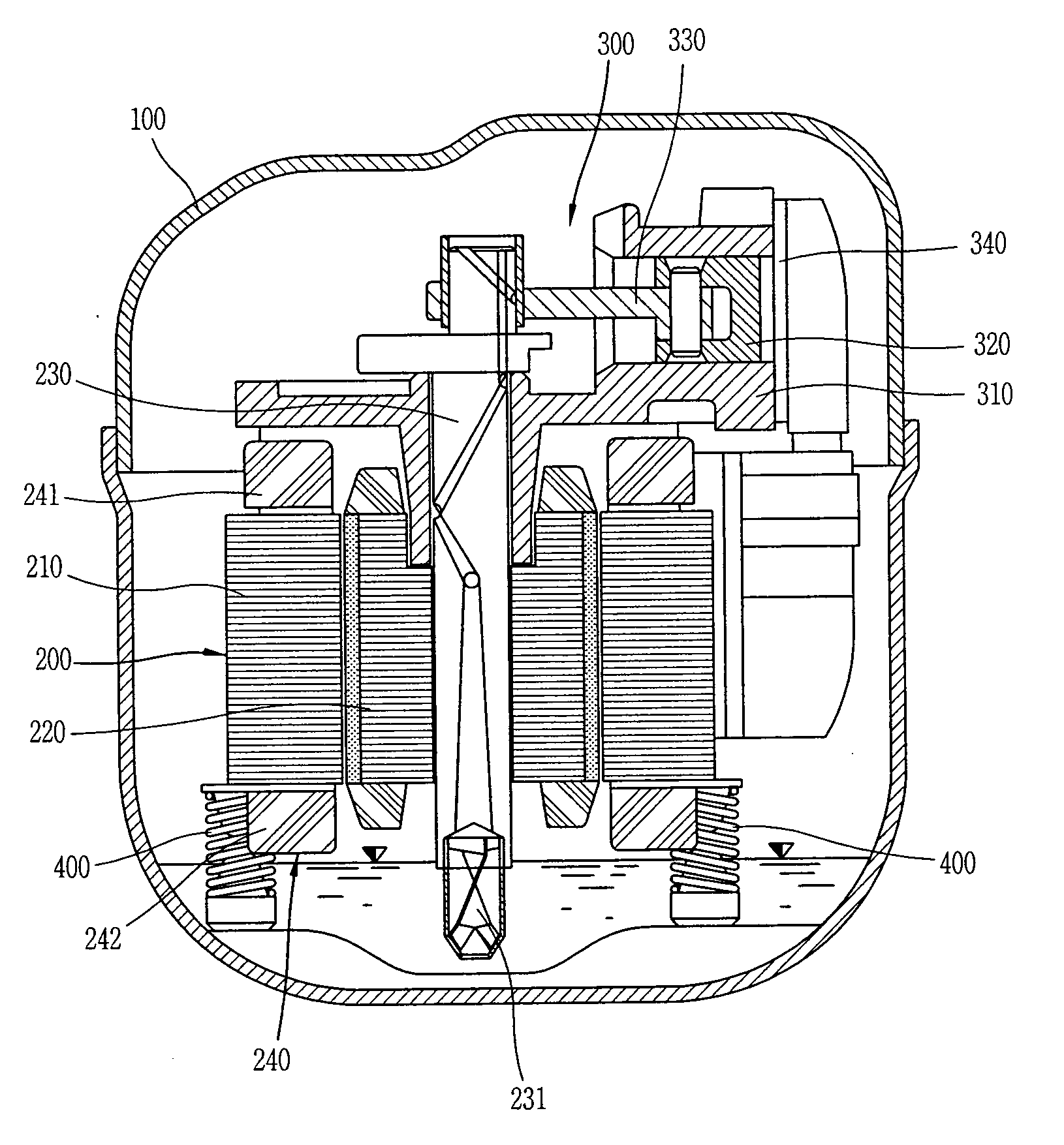
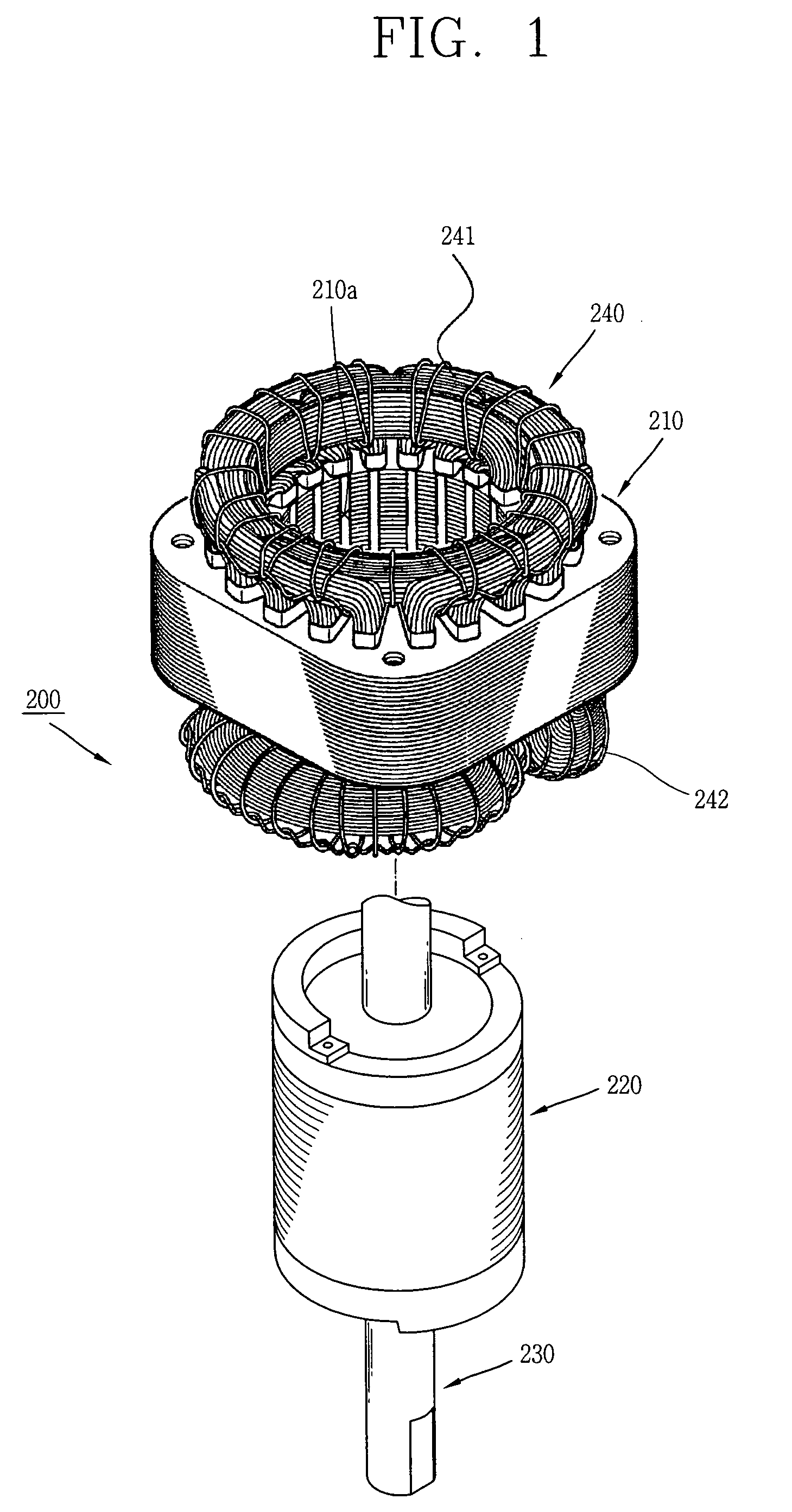
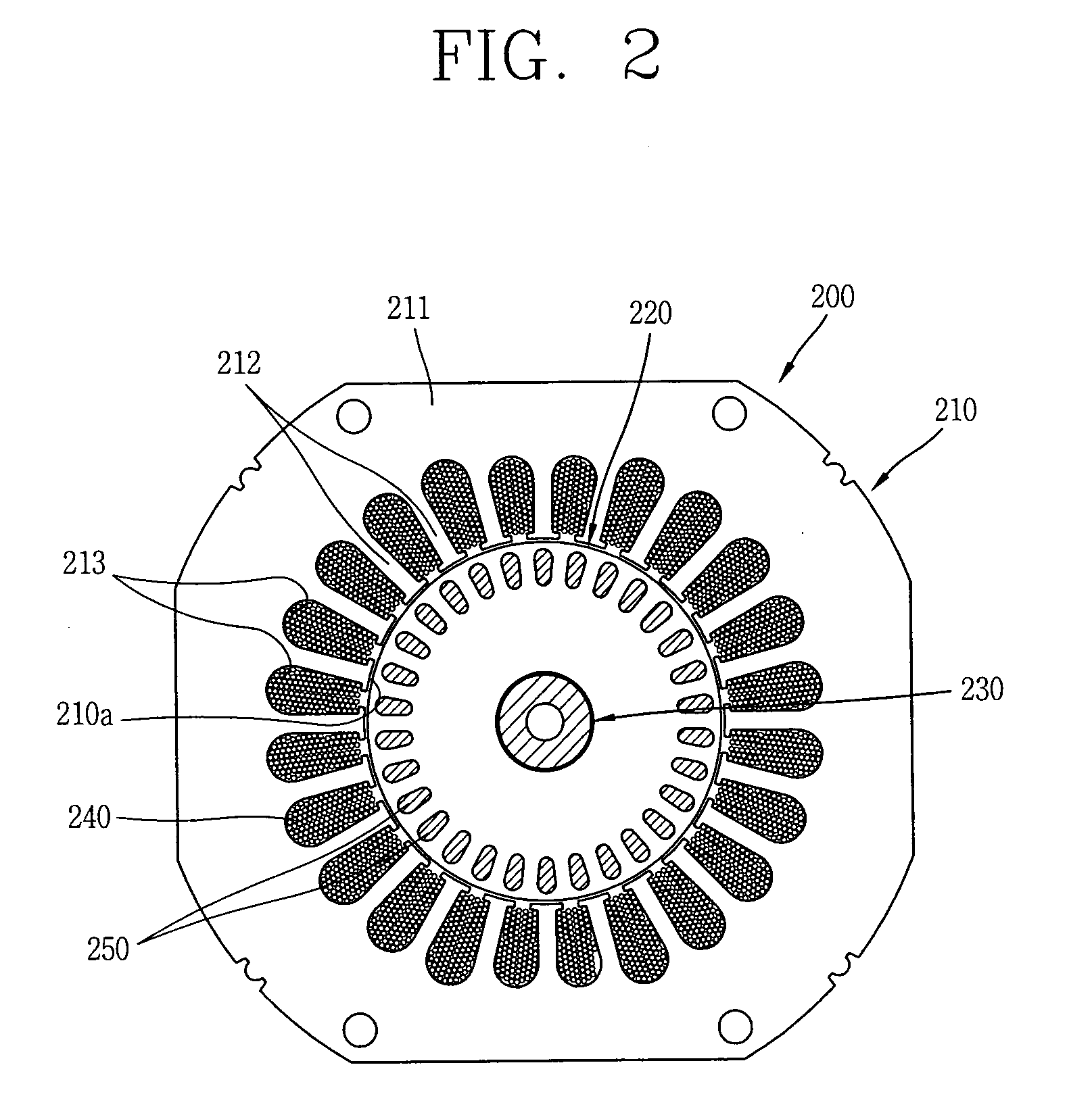
[0022]As shown in FIGS. 1 and 2, a motor 200 for a compressor according to the present invention may include a stator 210 fixed to a hermetic case of the compressor and having a coil 240 wound thereon, a rotor 220 rotatably inserted inside the stator 210 and having conductors 250 therein, and a rotational shaft 230 press-fitted in the center of the rotor 220 for transferring a rotational force to a compression unit of the compressor.

[0023]The stator 210 is formed by axially laminating plural sheets of stator core up to a certain height and welding them together. The plural sheets of stator core form a rotor insertion hole 210a having an outer circumferential surface with an approximately tetragonal shape (or it may be similar to a circular shape) and an inner circumferential surface ...


PUM


Abstract

Disclosed are a motor for a compressor and a hermetic compressor having the same. An aluminum coil cheaper than a copper coil is used in the motor for the compressor, a ratio between the aluminum coil and a stator core is set, and sectional areas of main and sub slot portions of the stator core and the numbers thereof are adjusted to be suitable for usage conditions, whereby fabricating costs of the motor for the compressor and the hermetic compressor can drastically be reduced and efficiencies thereof can be improved.

Description

TECHNICAL FIELD[0001]The present invention relates to a motor for a compressor and a hermetic compressor having the same.BACKGROUND ART[0002]In general, a refrigerator or an air conditioner, as small-sized home alliances, is provided with a compressor for compressing a refrigerant. A representative motor for the compressor which drives the compressor is a well-known induction motor. The induction motor includes a stator on which a coil is wound, a rotor having conductors in the form of a squirrel cage and rotatably inserted inside of the stator, and a rotational shaft press-fitted in the center of the is rotor for carrying a rotational force, generated by an interaction between a rotation magnetic field generated by an alternating current (AC) flowing in the coil of the stator and an induction current generated by the rotor, to a compression unit of the compressor.[0003]Each of the stator and rotor is configured such that plural sheets of thin stator core are stacked together to be ...

Claims


Application Information

Patent Timeline
IPC IPC(8): F04B35/04H02K17/16H02K23/36
CPCH02K1/165
Inventor JUNG, HAE-OKPARK, DONG-INSUNG, KI-SEOKLEE, JAE-HUNKIM, CHEOLSEO, SEONG-HUN
Owner LG ELECTRONICS INC
Why Eureka
Try Eureka