Pulley Device

a pulley and device technology, applied in the direction of bearing unit rigid support, hoisting equipment, gearing, etc., can solve the problems of accelerated deterioration of internal components of bearings, and increased risk of pollution penetrating into bearing chambers with the duration of use of the pulley devi

Active Publication Date: 2022-06-30
AB SKF
View PDF57 Cites 0 Cited by
  • Summary
  • Abstract
  • Description
  • Claims
  • Application Information

AI Technical Summary

Benefits of technology

[0006]More specifically, the present invention aims to provide a pulley device that is resilient in high-pollution conditions, particularly economical, easily and securely mounted, forming a non-detachable subassembly, and with a reduced axial and radial spatial requirement.
[0010]Thanks to the invention, an annular protection shield is mounted such as to be rigidly connected to the pulley device with a satisfactory concentricity, avoiding the design of complex pieces.
[0011]The pulley device, and more particularly the radial space between the coaxial rings of the bearing, is protected from the intrusion of pollution. The life and the quality of the mechanical linkage provided by the bearing are improved thereby.
[0012]Moreover, the shield forms an axial stop for the sleeve such as to ensure retention in the bore of the inner ring. The sleeve is mounted freely in the bore of the inner ring, i.e. with a radial clearance between an outer surface of the sleeve and an inner surface of the bore, but remains axially rigidly connected to the inner ring and therefore to the pulley device. The necessary tolerances thus require less precision giving a saving in time and a reduction in the manufacturing cost.

Problems solved by technology

Particles or other elements of pollution can however penetrate, which can accumulate over time in immediate proximity to the sealing means for the bearing.
Since the sealing means can become worn, the risk of the pollution penetrating into the bearing chamber increases with the duration of use of the pulley device.
This internal pollution can result in an accelerated deterioration of the components internal to the bearing, in particular the contact surfaces between the rolling elements and the rings.
Therefore, this can lead to a decrease in the quality of the rotating mechanical linkage provided by the pulley device, and a reduced life of the internal components thereof.
The risk of breakage, particularly in operation mode, is also greater.

Method used


Image

  • Pulley Device
  • Pulley Device
  • Pulley Device

Examples


first embodiment

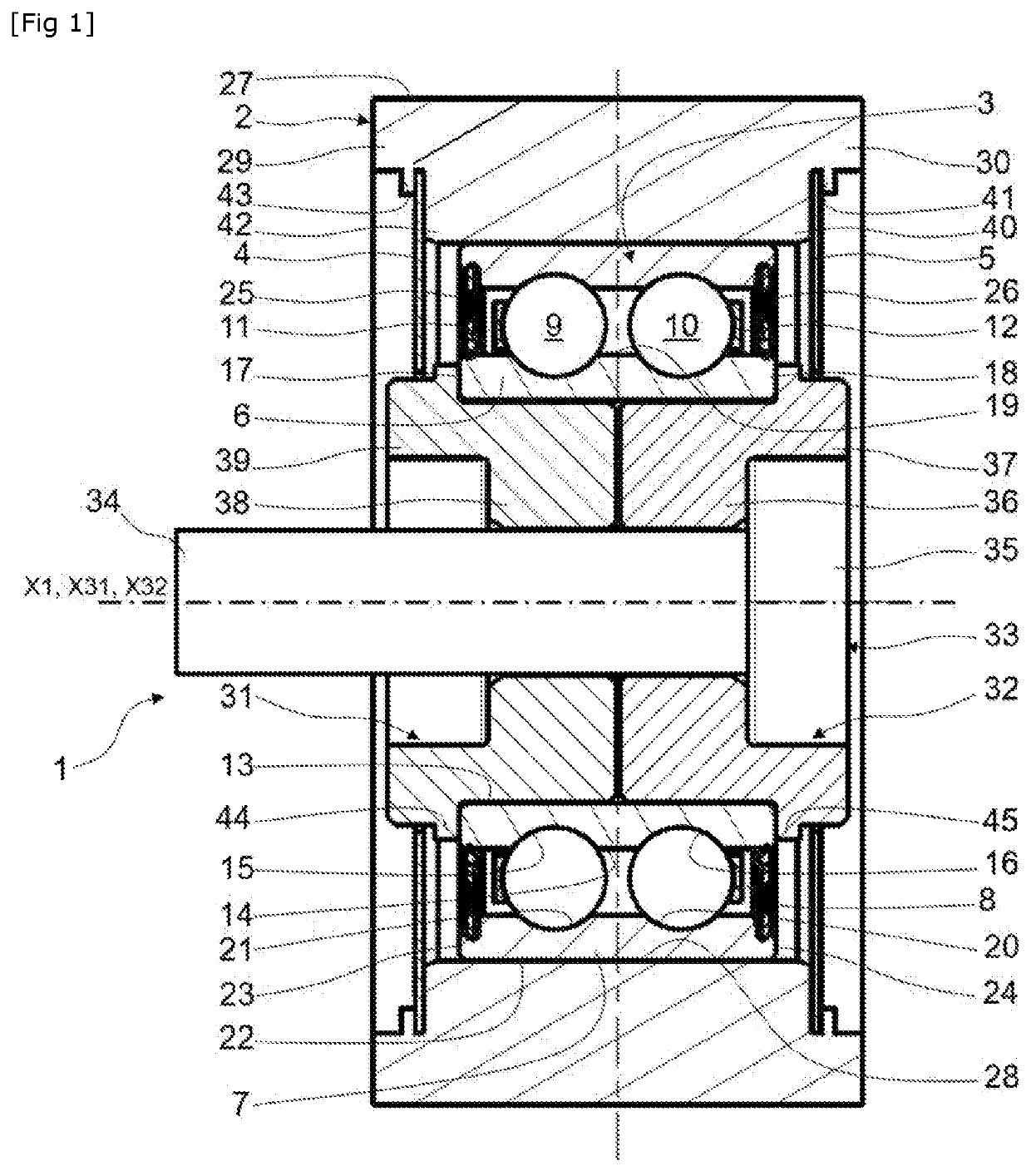
[0066]According to the invention first embodiment illustrated in FIG. 1, the outer first ends of the rear 4 and front 5 shields are rigidly connected to the pulley 2. In the example illustrated in FIG. 1, the outer first end of the front shield 5 rests axially against a collar 40 of the stepped and projecting front portion 30 of the pulley 2, and is held axially in the other direction by crimping portions 41 obtained via plastic deformations of the lateral edge of the portion 30. Similarly, the outer first end of the rear shield 4 rests axially against a collar 42 of the stepped and projecting rear portion 29 of the pulley 2, and is held axially in the other direction by crimping portions 43 obtained by plastic deformations of the lateral edge of the portion 29. Advantageously, crimping portions are circumferentially regularly distributed over the axially projecting rear 29 and front 30 portions of the pulley 2. Alternatively, the shields can be rigidly connected to the axially proj...

second embodiment

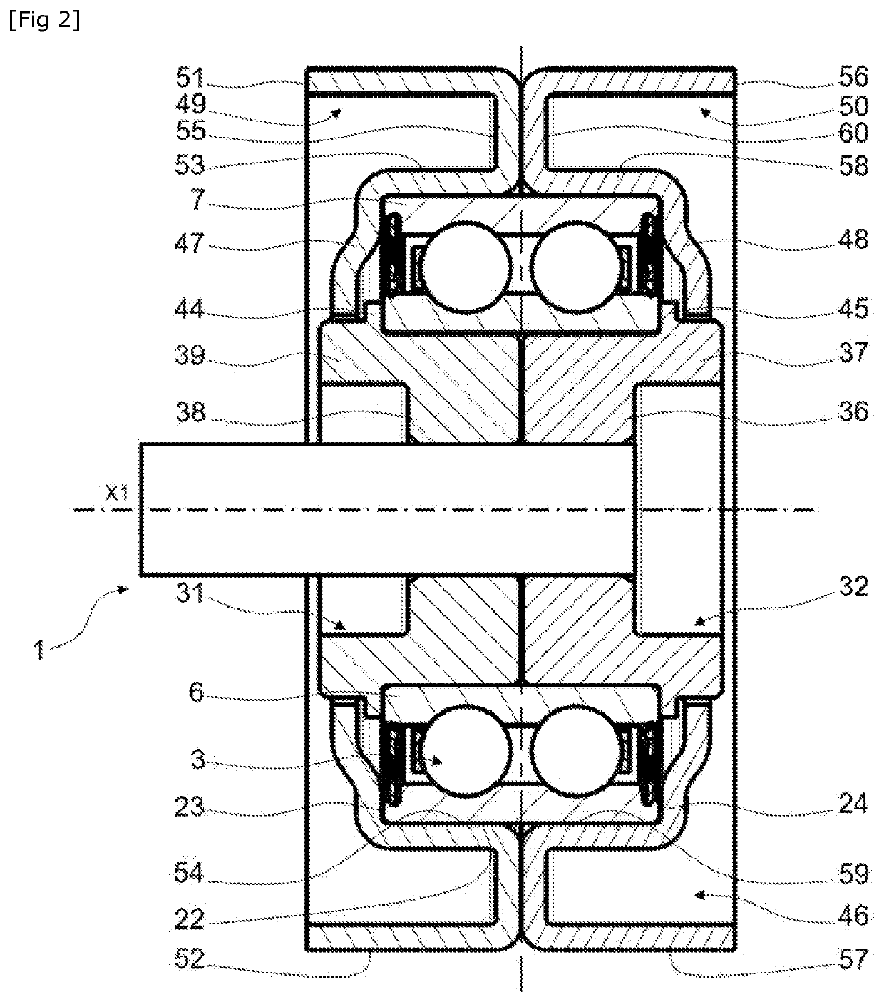
[0068]A second embodiment is illustrated in FIG. 2. The pulley device 1 according to this alternative embodiment differs from the previous embodiment illustrated in FIG. 1 in that a pulley 46 and rear 47 and front 48 shields form a single-piece assembly.

[0069]More precisely, the pulley 46 comprises a rear pulley element 49, and a front pulley element 50.

[0070]The rear pulley element 49 comprises an outer annular portion 51 with an outer cylindrical surface 52 that can engage a transmission means, and a cylindrical bore (not referenced). The element 49 also comprises an inner annular portion 53 with a cylindrical bore 54 tightly mounted on the outer cylindrical surface 22 of the rotating outer ring 7 of the bearing 3, and an outer cylindrical surface (not referenced). The outer annular portion 51 is tubular and moreover has a greater diameter than the inner annular portion 53 which is also tubular, the outer annular portion 51 radially surrounding the inner annular portion 53. The ou...

third embodiment

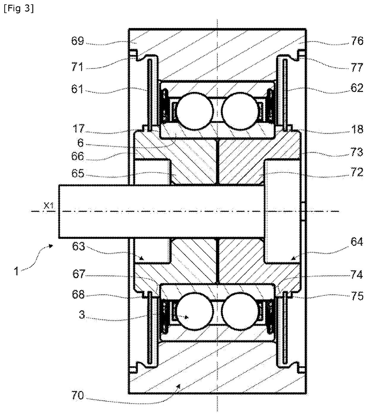
[0083]A third embodiment is illustrated in FIG. 3. It differs from the two embodiments described previously in that the rear 61 and front 62 shields are rigidly connected to the rear 63 and front 64 sleeves, respectively.

[0084]More precisely, the rear sleeve 63 comprises a cylindrical body 65 housed in the inner ring 6, and an outer radial skirt 66 axially projecting rearward with respect to the rear lateral surface 17 of the inner ring 6 of the bearing 3. The skirt 66 comprises a radially projecting collar 67. An inner end of the rear shield 61 is held to axially bear against the collar 67 via crimping portions 68 obtained by plastic deformations of the lateral edge of the skirt 66. The rear shield 61 is thus rigidly connected to the rear sleeve 63. The rigid connection can be achieved by any other suitable means, for example by sticking.

[0085]The rear shield 61 extends mainly radially from the inner end rigidly connected to the rear sleeve 63 toward an outer end coming into immedi...


PUM


Abstract

A pulley device for a transmission element having a pulley, a bearing, and at least one sleeve mounted freely in the bore of the inner ring of the bearing. The pulley device includes at least one annular protection shield, the shield retained axially in a first element from the pulley and coming into immediate proximity with the other element, the other element having at least one shoulder projecting radially ensuring that it is axially retained with the shield.

Description

TECHNICAL FIELD OF THE INVENTION[0001]The present invention relates to a pulley device. The field of the invention is that of tension rollers for tensioning a chain or a belt for transmission of movements, rollers, belt tighteners, loose pulleys, and any other rotation transmission support means.BACKGROUND OF THE INVENTION[0002]In a known manner, such a pulley device can comprise a bearing, a pulley, and a fastening screw. The bearing generally comprises a fixed inner ring with a bore through which the screw passes, a rotating outer ring surmounted by the pulley, and at least one row of rolling elements inserted between the rings. The screw comprises a head and a threaded shaft. The screw passes through the inner ring of the bearing such that the threaded shaft thereof enters a tapped hole provided in a support, for example an engine block.[0003]It is recommended to avoid a mechanical contact between the rotating elements of the bearing and the support which can particularly be plac...

Claims


Application Information

Patent Timeline
Patent Type & Authority Applications(United States)
IPC IPC(8): F16H55/36F16C19/08F16H7/20
CPCF16H55/36F16H7/20F16C19/08F16H55/46F16H55/49F16C33/7806F16C33/782F16J15/16F16H55/44F16H2007/0865F16C13/006F16C33/78F16C33/7863F16C35/073F16C2361/63
Inventor ARNAULT, BENOITTRONQUOY, NICOLAS
Owner AB SKF
Why Eureka
Try Eureka