Disc clamp with snap fit for a disc drive

a technology of disc drives and clamps, applied in the field of magnetic disc drives, can solve the problems of generating unacceptable operational errors, physical distortion of information storage discs, and disassembly of the periphery of the clamp, and achieves the effect of simple and cheap manufacturing, easy and secure mounting

Inactive Publication Date: 2008-05-27
MINEBEAMITSUMI INC
View PDF6 Cites 10 Cited by
  • Summary
  • Abstract
  • Description
  • Claims
  • Application Information

AI Technical Summary

Benefits of technology

[0006]It is the object of the present invention, to provide a disc clamp for a disc drive which is simple and cheap to manufacture, and which can be easily and securely mounted on the spindle hub.

Problems solved by technology

However, the screw is a discrete source of the clamping force, thus the distribution of the downward force around the periphery of the clamp, against the adjacent disc is exerted in a non-uniform manner.
Non-uniform clamping force can generally cause variations in the load force applied and, as a result, can cause the information storage disc to be physically distorted.
Distortion of the disc can lead to generation of unacceptable operational errors during recording and reproduction of data on the information storage disc.
Further, the use of screws is relative costly.
This relatively high torque requirement can lead to a number of problems including over-stressing the spindle shaft bearing, stripping threads, and the generation of particles during the torqueing process.
These high-torque related problems can damage the bearing and lead to failure of the spindle motor.
Some screw-less disc clamps have been developed in attempts to overcome these shortcomings, but without completely satisfactory results.
Often, such screw-less clamps are complicated, and difficult and expensive to manufacture and to mount on the spindle hub.

Method used


Image

  • Disc clamp with snap fit for a disc drive
  • Disc clamp with snap fit for a disc drive
  • Disc clamp with snap fit for a disc drive

Examples


Embodiment Construction

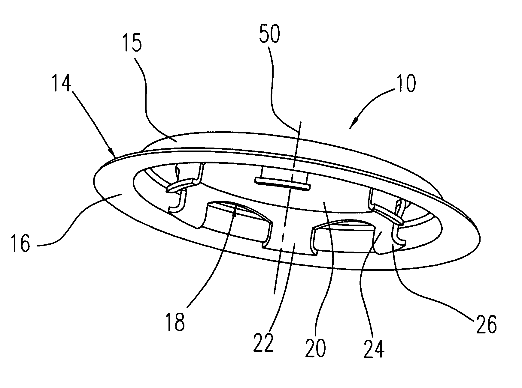
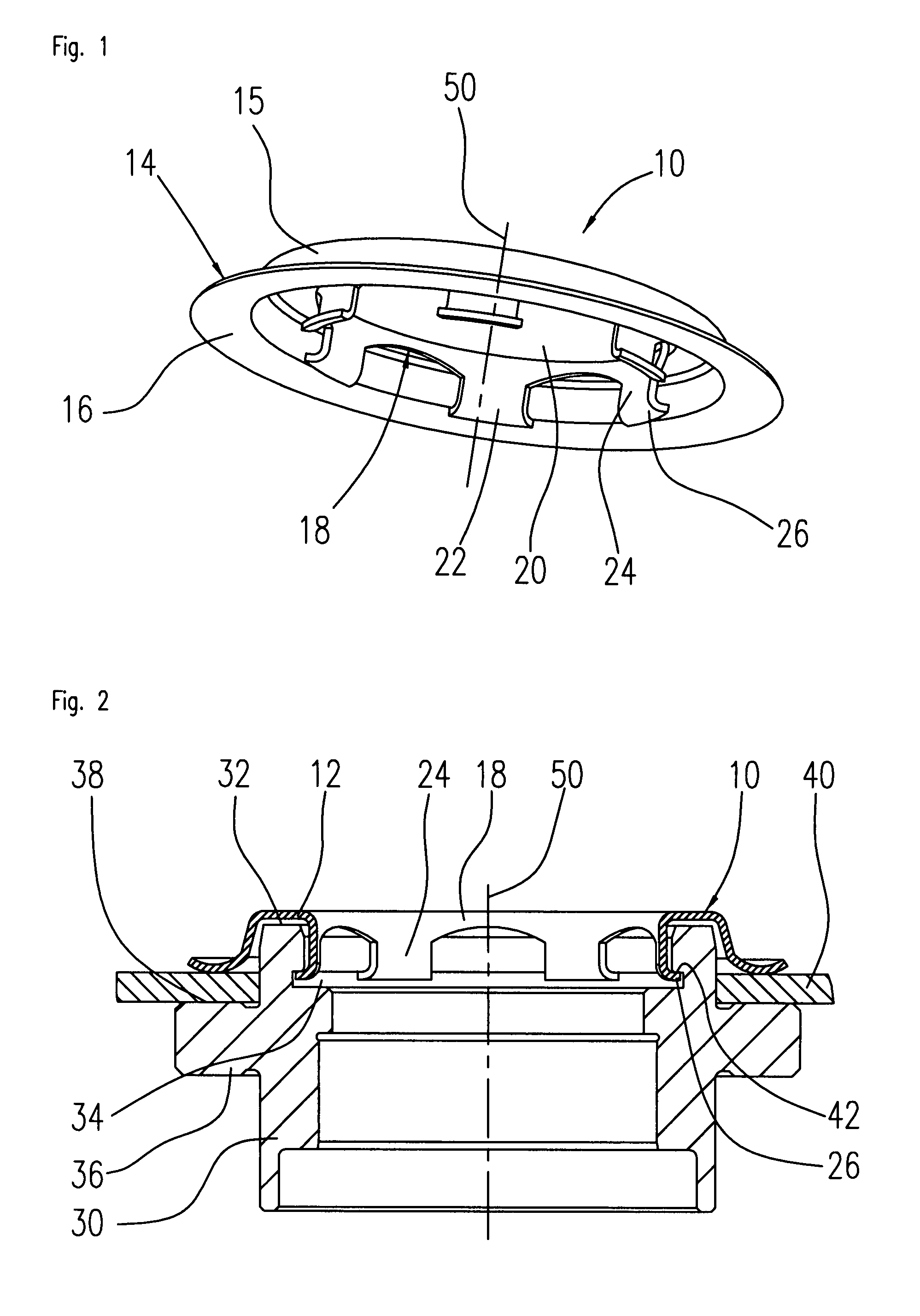
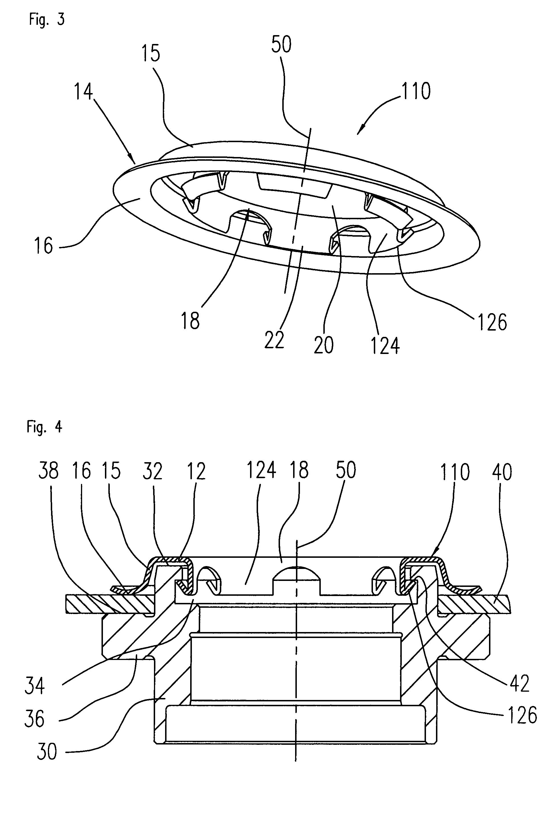
[0023]The disc clamp 10, as shown in FIG. 1, is a spring member having a generally annular shape. The disc clamp 10 consists of an annular body portion 12, an outer peripheral clamping portion 14 and a centering portion 18. The outer clamping portion 14 consists of a first portion 15 protruding substantially perpendicular from the outer rim of the body portion 12 and ending in a lower contact surface 16 which is substantially parallel to the body portion 12.

[0024]The disc clamp 10 further includes a centering portion 18 around a central aperture 20. The centering portion comprises a plurality of centering tabs 22 that are connected to the inner periphery of the body portion 12. Preferably, each centering tab 22 is generally hook shaped in cross section.

[0025]A first portion 24 of the centering tab 22 extend downwardly substantially perpendicular to the body portion 12 defining the boundary of the central aperture 20. A-second tab end portion 26 connects in an angle to the end of the...


PUM

PropertyMeasurementUnit
angleaaaaaaaaaa
clamping forceaaaaaaaaaa
inner perimeteraaaaaaaaaa

Abstract

The invention relates to a disc clamp for mounting an information storage disc to a rotating hub of a spindle motor assembly, and a disc drive spindle hub assembly comprising said disc clamp. The disc clamp comprises an annular body portion, an inner centering portion defining a central aperture, and an annular outer peripheral clamping portion. The inner centering portion having a series of centering tabs disposed about an inner circumference of the body portion. Each centering tab includes a first tab portion extending substantially perpendicular to the body portion of the clamp, and a second tab end portion extending in an angle from the first tab portion. The centering tabs contacting an inner circumferential surface and being in a snap-fit engagement with the hub The outer peripheral portion contacting the information storage disc when the disc and the clamp are installed on the top portion of the hub.

Description

FIELD OF THE INVENTION [0001]The present invention generally relates to magnetic disc drives, and particularly to a disc drive clamp for mounting at least one information storage disc on a rotating part of a disc drive spindle motor.BACKGROUND OF THE INVENTION [0002]Disc drives are data storage devices that store digital data in magnetic form on a rotating information storage disc. Modern disc drives include one or more rigid discs that are coated with a magnetizable medium and mounted on the hub of a spindle motor for rotation at a constant high speed. For being able to reliably reading and writing information on the disc by means of a read / write head it is critical that the information storage disc is well fixed and centered on the hub of the spindle motor.[0003]Spindle motor assemblies often utilize a rotating spindle hub journaled to a non-rotatable spindle shaft. A disc clamp is typically secured to the rotating spindle hub to exert a downward axial force on the mounted informa...

Claims


Application Information

Patent Timeline
Patent Type & Authority Patents(United States)
IPC IPC(8): G11B17/02
CPCG11B17/0284
Inventor ENGESSER, MARTINSCHWAMBERGER, STEFAN
Owner MINEBEAMITSUMI INC
Why Eureka
Try Eureka