Secure Rack-Based Storage Enclosure

a rack-based storage and enclosure technology, applied in the field of enclosures, can solve the problems of difficult installation and maintenance of equipment in the enclosure, unsecured racks, and inability to secure external security, and achieve the effects of convenient mounting locations, convenient installation, and servi

Inactive Publication Date: 2016-02-11
GRIFFITH ROBERT J
View PDF10 Cites 6 Cited by
  • Summary
  • Abstract
  • Description
  • Claims
  • Application Information

AI Technical Summary

Benefits of technology

[0005]A secure rack-based storage enclosure is constructed so as to provide wide access to the front of the enclosure so that telecommunications equipment can be easily install, mounted, and serviced in the enclosure. The enclosure further prevents unauthorized access to the telecommunications equipment, and includes left and right side panels, top and bottom panels, an open back and front, an interior, and a door pivotally mounted to the front. Rear flanges extend between the top and bottom panels proximate to the back of the enclosure, and the rear flanges cooperate with each of the top and bottom panels to define open notches extending into the interior of the enclosure away from and in communication with the open back of the enclosure. The notches receive posts of the rack so that the enclosure can be easily and securely mounted to the rack. Intermediate flanges extend between the top and bottom panels, and are disposed between the rear flanges and the front of the enclosure. The intermediate flanges provide convenient mounting locations for telecommunications equipment mounted in the enclosure, independent of the mounting to the rack. A hinge assembly couples the door to the front panel proximate one of the left and right side panels. An elongate member is pivoted to the other of the left and right side panels opposite the hinge assembly.

Problems solved by technology

Most racks are unsecured, in that there are no access restrictions to the equipment in the rack.
In some cases, however, such external security may not be present, and a secure enclosure for the equipment on the rack may be desired.
However, such housings and doors, while providing security, also make installation and maintenance of equipment in the enclosure more difficult.
In large facilities or locations where multiple racks are placed tightly together, access to the enclosure can be made especially difficult if the door to the enclosure cannot be swung entirely open.

Method used


Image

  • Secure Rack-Based Storage Enclosure
  • Secure Rack-Based Storage Enclosure
  • Secure Rack-Based Storage Enclosure

Examples


Embodiment Construction

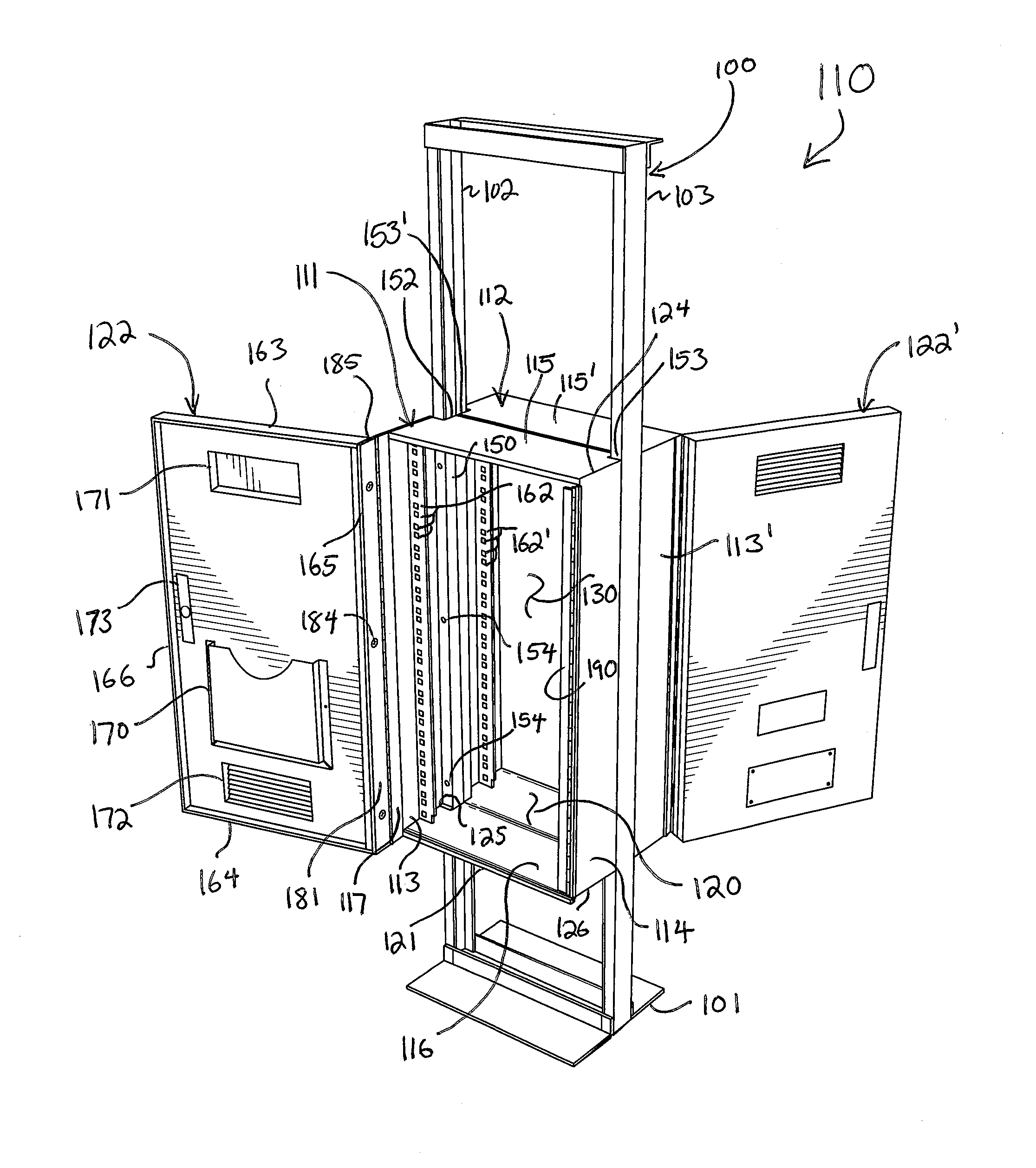
[0020]Reference now is made to the drawings, in which the same reference characters are used throughout the different figures to designate the same elements. FIG. 7 illustrates an embodiment of an enclosure system 110 formed from a front enclosure 111 and a back enclosure 112. The enclosure system 110 is suitable for use with a telecommunications rack 100 including a base 101 and opposed left and right posts 102 and 103 extending upwardly from the base 101. The front and back enclosures 111 and 112 are identical and symmetric, and as such, discussion will generally be limited to the front enclosure 111 (or, simply, “the enclosure 111”). Because the front and back enclosures 111 and 112 are identical, the same reference characters used to describe the various structural elements and features of the front enclosure 111 will be used to describe and identify corresponding identical structural elements and features, but will be marked with a prime (“′”) symbol, so as to designate and dif...


PUM


Abstract

A secure rack-based storage enclosure for preventing access to telecommunications equipment includes left and right side panels, top and bottom panels, an open back and front, an interior, and a door pivotally mounted to the front. Rear flanges extend between the top and bottom panels proximate to the back of the enclosure, and the rear flanges cooperate with each of the top and bottom panels to define open notches extending into the interior of the enclosure away from and in communication with the open back of the enclosure. Intermediate flanges extend between the top and bottom panels, and are disposed between the rear flanges and the front of the enclosure. A hinge assembly couples the door to the front panel proximate one of the left and right side panels. An elongate member is pivoted to the other of the left and right side panels opposite the hinge assembly.

Description

CROSS-REFERENCE TO RELATED APPLICATIONS[0001]This application is a continuation-in-part of and claims the benefit of prior U.S. patent application Ser. No. 13 / 921,176, filed Jun. 18, 2013, which is hereby incorporated by reference.FIELD OF THE INVENTION[0002]The present invention relates generally to enclosures, and more particularly to secure enclosures.BACKGROUND OF THE INVENTION[0003]Telecommunications equipment is conventionally mounted on a two-post rack which can accommodate a variety of types of telecommunication equipment. A rack is a frame for mounting equipment, and is a convenient, universal, and sturdy assembly on which to do so. A rack typically includes a base and two upwardly-extending metal posts; most but not all are nineteen inches wide and several feet tall. Most racks are unsecured, in that there are no access restrictions to the equipment in the rack. This is because, often, racks are stored behind closed and locked doors, or are located in storage facilities wi...

Claims


Application Information

Patent Timeline
Patent Type & Authority Applications(United States)
IPC IPC(8): A47B81/00A47B96/00
CPCA47B96/00A47B81/00H05K5/0208H05K7/186
Inventor GRIFFITH, ROBERT, J.
Owner GRIFFITH ROBERT J
Why Eureka
Try Eureka