Baler connectable to a tractor and method

a technology of connecting bales and tractor, which is applied in the field of balers, can solve the problems of wasting time, affecting the operation of driving the tractor, and affecting the quality of bales,

Pending Publication Date: 2022-07-14
KVERNELAND GRP RAVENNA
View PDF0 Cites 0 Cited by
  • Summary
  • Abstract
  • Description
  • Claims
  • Application Information

AI Technical Summary

Benefits of technology

[0026]Hence, the bale formation is performed firstly in the first part of the baling chamber, then during the transferring from the first part to the second part, then it is completed in the second part. This solution provides a non-stop bale which allows to form a uniform bale, by constantly feeding the crops during the formation of the bale and, also to prevent instantaneous expansions of the bale and to ease the transferring.
[0032]Hence, the method provides a non-stop baling process characterized by a good uniformity of crops distribution and a good average pressure in the formed bale. Also, the transferring of the bale is particularly easy.
[0035]This positioning of the binder makes the access to the fastening element reservoir roll more comfortable; in fact, the user may easily slide out a finished roll and slide in a new roll, without any need for raising heavy rolls.
[0036]Also, thanks to the positioning of the binder under de baler, it is possible to feed the fastening element to the bale through a passage defined between a starter roller and a portion of the frame, avoiding to interrupt the belt elsewhere.

Problems solved by technology

This stop implies wastes of time and additionally complicates the operations of driving the tractor.
Generally speaking, fixed balers have several drawbacks: the internal density of the formed bale is limited by the fact that at the beginning of the forming process, the crops are not compressed inside the chamber.
Further, the final dimension of the bale is fixed, thus it is not adaptable according to user's desires.
In this solution, a high degree of integration of sensors and electronics increases the final cost and reduces the reliability of the machine; moreover, the maximum bale density achievable is limited by the fact that the baling chamber has fixed dimension.
In these solutions, the horizontal moving of the bale to the back chamber requires high complexity of the transfer means, implying high power consumption and long overall baling cycle time.
This baler has as a drawback a huge dimension (especially in a longitudinal direction) resulting in high costs.
Another disadvantage is that the material pre-pressed in the storage space expands again after the transfer into the empty pressing chamber and desired bale densities are not achieved.
Further, the crops need to travel for a long distance into the storage space (from a feeding rotor up to the pressing chamber), resulting in high energy consumption.
This solution has as a drawback the difficulty of filling and emptying the storage means; in fact, the crops that are fed to the storage means tend to form an agglomerate that is difficult to release and feed to the rear area.
Also, the bale formation is not uniform, because in a first step two flows of crops are fed to the bale (one from the pick-up device and one from the storage means), and in a second step a single flow of crop (from the pick-up device) is fed to the bale.
An additional issue in variable balers is the positioning of the binding device: while in fixed or in semi-variable balers it is sufficient to insert the binding material between two of the fixed rollers of the baling chamber (like in the fixed baler of the above-mentioned document EP300854A1 or in the semi-variable baler of the above-mentioned document DE102011109893A1), in variable balers it is difficult to find a room for feeding the binding material towards the bale.
Another issue in variable and semi-variable balers is that the belt requires a quite complex design in order to create a passage through which the bale can be discharged.
In the above-mentioned document DE102011109893A1, the whole belt is lifted in order to discharge the bale; this mechanism requires high strengths to lift the whole belt resulting in high complexity of the machine.
However, the presence of two belts makes the compressing of the bale less effective and the machine control more complex.

Method used


Image

  • Baler connectable to a tractor and method
  • Baler connectable to a tractor and method
  • Baler connectable to a tractor and method

Examples


Embodiment Construction

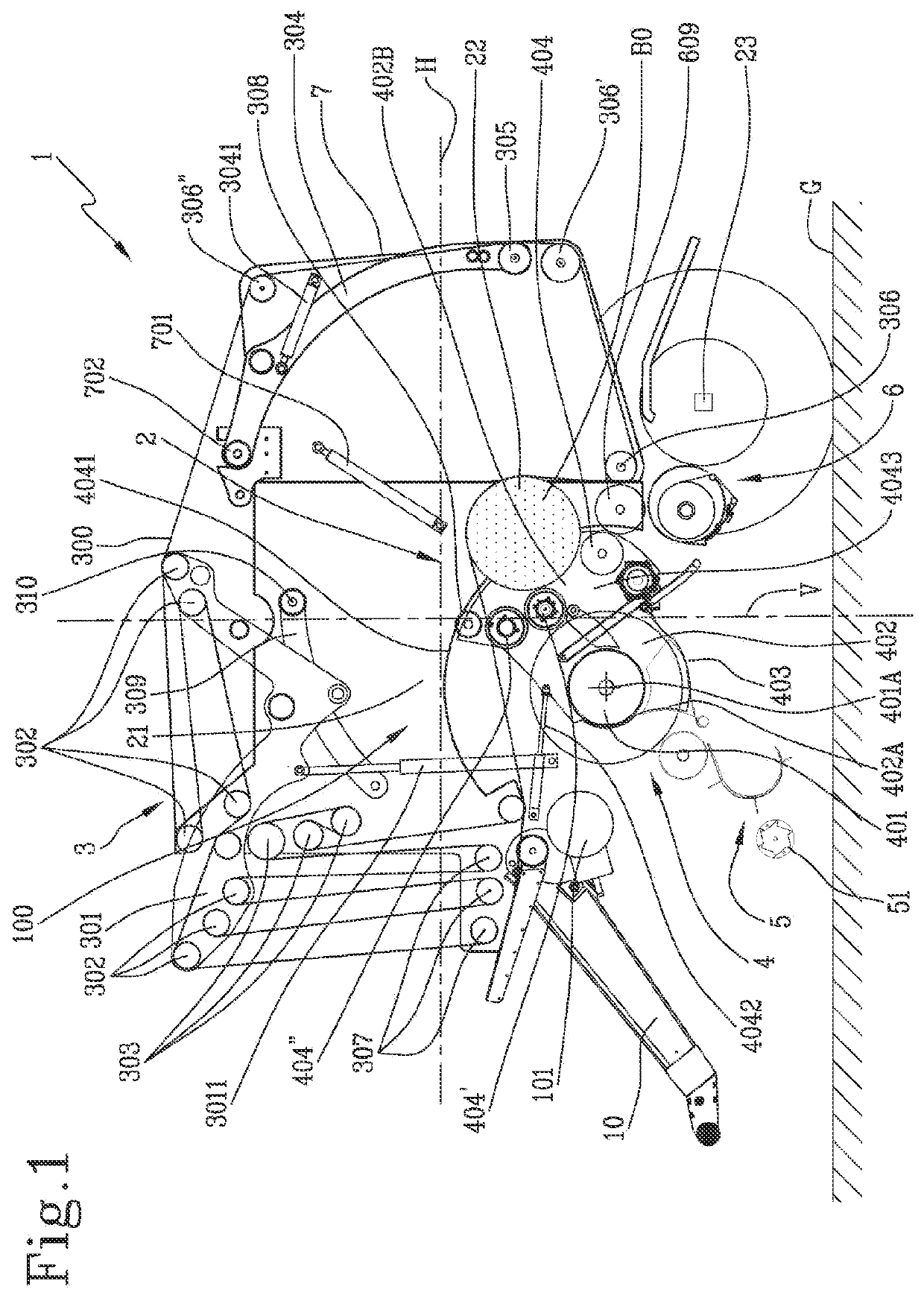
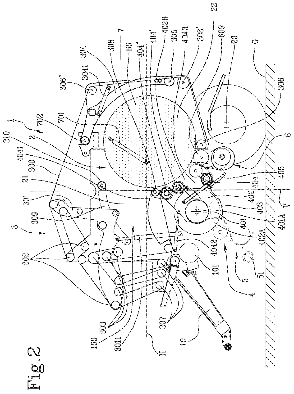
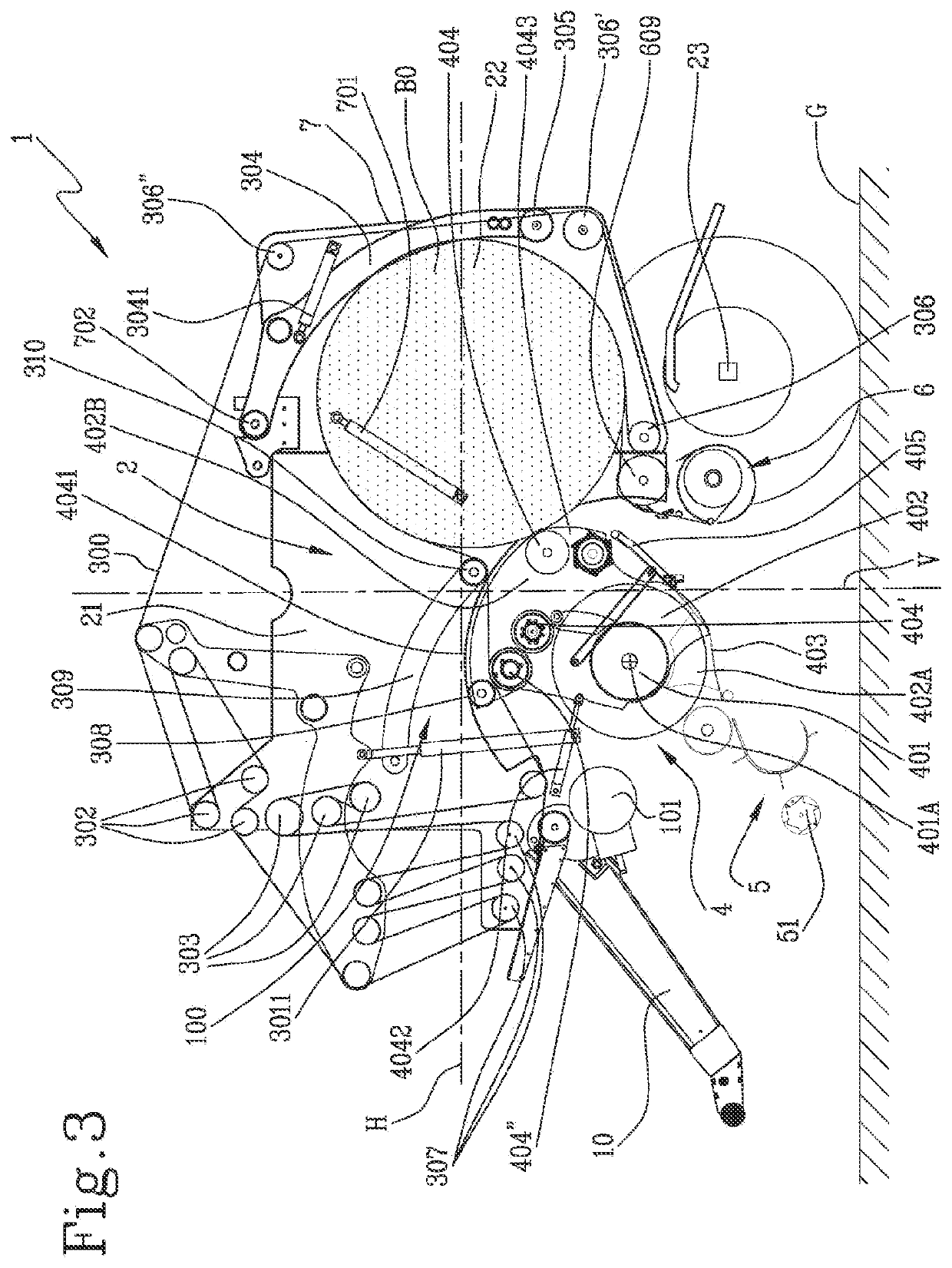
[0107]With reference to the accompanying drawings, the numeral 1 denotes a baler, according to the present disclosure.

[0108]The baler 1 includes a tongue 10 connectable to a tractor. The tongue 10 is configured to allow the tractor to tow the baler 1.

[0109]The baler 1 comprises a drive shaft. The drive shaft, in an embodiment, is a cardan shaft. The baler 1 includes a gearbox 101. The drive shaft is configured to transmit mechanical rotation from a motor of the tractor to the baler 1, through the gearbox 101.

[0110]The baler 1 comprises a frame 100 including a baling chamber 2. The frame 100 surrounds the baling chamber 2. The baling chamber includes a first part 21 and a second part 22. The baling chamber 2 is configured for receiving crops to form a bale B.

[0111]The baler 1 comprises a wheel axle 23; the frame 100 is supported on the wheel axle 23.

[0112]The baler 1 comprises a conveying assembly 3. The conveying assembly 3 includes a belt 300.

[0113]The conveying assembly 3 includes...


PUM


Abstract

A baler connectable to a tractor for providing round bales, comprises: a baling chamber including a first part, and a second part; a pick-up device; a feeding system, including a feeding channel movable between a first configuration and a second configuration, wherein, in the first configuration of the feeding system, the feeding channel has a first orientation so that the outlet of the feeding channel is opened to the first part of the baling chamber, and, in the second configuration of the feeding system, the feeding channel has a second orientation, so that the outlet of the feeding channel is opened to the second part of the baling chamber, wherein the feeding system further includes a plurality of starter rollers, arranged at the outlet of the feeding channel.

Description

TECHNICAL FIELD[0001]This invention relates to a baler connectable to a tractor for providing round bales and to a method for producing round bales in a baler connected to a tractor.BACKGROUND ART[0002]Balers are configured to produce a bale over a cycle including a first step of picking up crops from a field, feeding them to a baling chamber and rotating them in the baling chamber to form a bale, and a second step, of binding the formed bale with a fastening element (for instance, a net). Traditionally, during the first step the baler moves forward in the field, while during the second step the baler stops for a period of dozens of seconds, until the bale is bound and is therefore discharged from the baler. This stop implies wastes of time and additionally complicates the operations of driving the tractor.[0003]Continuous (or non-stop) balers have been developed in order to avoid the stop of the baler for binding the bale, thus saving time and simplifying the operations of driving ...

Claims


Application Information

Patent Timeline
Patent Type & Authority Applications(United States)
IPC IPC(8): A01F15/07
CPCA01F15/0705
Inventor VARLEY, SEAMUS
Owner KVERNELAND GRP RAVENNA
Why Eureka
Try Eureka