Lens autofocus actuating device

a technology of actuating device and lens, which is applied in the direction of mounting, focusing aid, instruments, etc., can solve the problems of affecting the overall focusing effect and optical performance, and the difficulty of controlling position using shape-memory alloy wire, and achieve the effect of accurate execution of focus control

Pending Publication Date: 2022-07-21
TDK TAIWAN
View PDF0 Cites 0 Cited by
  • Summary
  • Abstract
  • Description
  • Claims
  • Application Information

AI Technical Summary

Benefits of technology

[0007]In view of the foregoing, one of the objects of the present invention is to provide a lens autofocus actuating device, which can regulate the dynamic tilt of the lens in the process of focusing and then accurately execute the focus control.
[0011]In summary, the lens autofocus actuating device of the present invention is to move the lens carrier relative to the base along the optical axis by using the guide rail unit and two groups of shape-memory alloy wires. In addition, the lens autofocus actuating device can limit the tilt angle of the lens carrier while it is moving by using the position-limiting members of the guide rail unit that are uniformly disposed on the fixing ring together with each group of balls, so as to realize a more accurate autofocusing of the lens.

Problems solved by technology

However, due to the nonlinear deformation curve and input current, as well as hysteresis, it is difficult to control position using the shape-memory alloy wire.
In the process of moving the lens module, however, controlling its dynamic tilt will affect the overall focusing effect and optical performance.

Method used


Image

  • Lens autofocus actuating device
  • Lens autofocus actuating device
  • Lens autofocus actuating device

Examples


Embodiment Construction

[0020]Reference will now be made to the drawings to describe various inventive embodiments of the present disclosure in detail, wherein like numerals refer to like elements throughout.

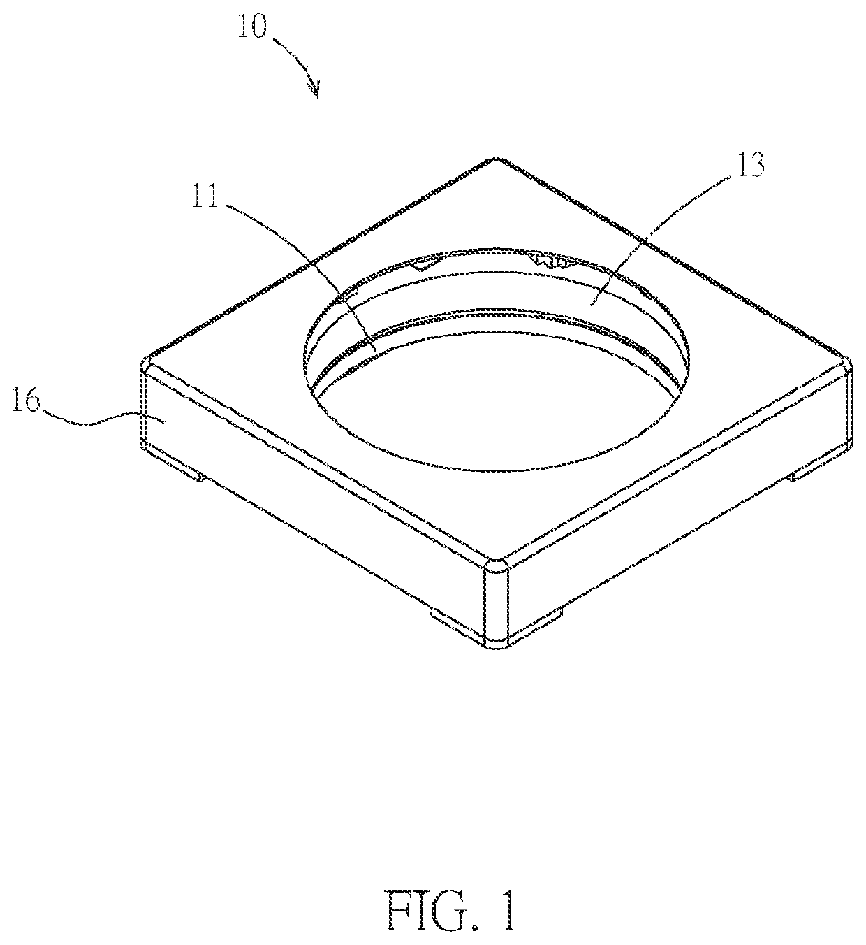
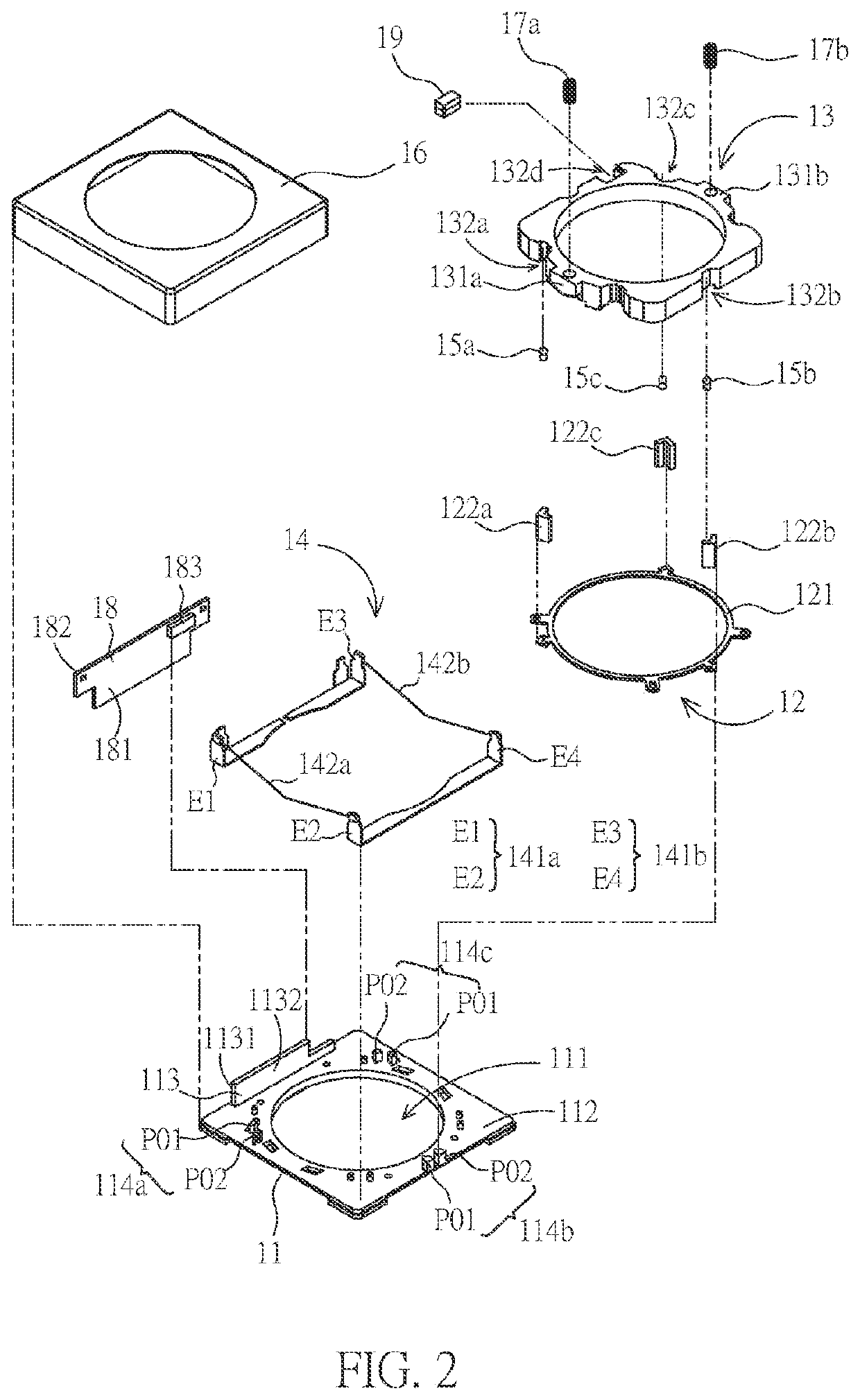
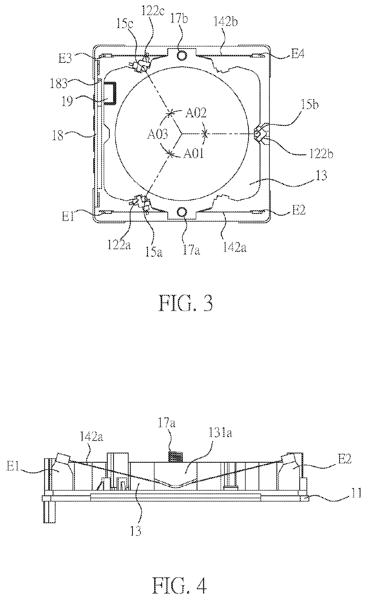
[0021]FIG. 1 is an appearance diagram of a lens autofocus actuating device 10 of the first embodiment in the present invention. FIG. 2 is an exploded diagram of the members of the lens autofocus actuating device 10. FIG. 3 is a top view diagram of the lens autofocus actuating device 10. FIG. 4 is a side view diagram of the lens autofocus actuating device 10.

[0022]Please refer to both FIG. 1 and FIG. 2, the lens autofocus actuating device 10 includes a base 11, a guide rail unit 12, a lens carrier 13, an actuating member 14, three groups of ball 15a, 15b and 15c, a shell 16, two resilient members 17a and 17b, a circuit board 18 and a magnetic member 19.

[0023]The base 11 has a slightly flat, rectangular shape, and has a central through hole 111 in the center. An upper surface 112 of the base 11 is provid...


PUM


Abstract

A lens autofocus actuating device includes a base, a guide rail unit, a lens carrier, an actuating member, a plurality of balls, and a shell. The base includes an upper surface. The guide rail unit is disposed on the upper surface of the base. The lens carrier is disposed above the base. The lens carrier is located between a plurality of position-limiting members. The actuating member is disposed on the upper surface of the base. The actuating member comprises two electrode terminal pairs and two shape-memory alloy wires. The balls are divided into groups. The shell is connected to the base.

Description

CROSS REFERENCE TO RELATED APPLICATIONS[0001]This application is a Continuation Application of U.S. patent application Ser. No. 16 / 830,500, filed on Mar. 26, 2020, which claims priority under 35 U.S.C. § 119(a) on Taiwan Patent Application No. 108114645 filed on Apr. 26, 2019, the entirety of which is incorporated by reference herein.BACKGROUND OF THE INVENTIONField of the Invention[0002]The present invention relates to a lens actuating device, in particular, it relates to a lens autofocus actuating device that cooperates with a shape-memory alloy (SMA).Description of the Related Art[0003]The autofocus actuating device of the mobile phone camera module is one of the integral standard configurations of current smartphone. The smartphone needs to move the lens module to complete autofocus during shooting.[0004]The design of an autofocus actuator involves a plurality of different technologies, including equipment such as a voice coil motor (VCM), a piezoelectric motor, and shape-memory...

Claims


Application Information

Patent Timeline
Patent Type & Authority Applications(United States)
IPC IPC(8): G02B7/09G02B7/02
CPCG02B7/09G02B7/026F03G7/065G02B7/08G03B13/36
Inventor CHIU, CHI-WEI
Owner TDK TAIWAN
Why Eureka
Try Eureka