Bone implant handling instrument for placing a bone implant in an operative position

a technology for putting bone implants and handling instruments, which is applied in the field of bone implants, can solve the problems of inability to easily insertion the implant at the location of the projections using only the device, inability to achieve flush insertion, and inability to achieve the alignment and/or degree of bone purchase by the projections in a manner that is not easy to achieve,

Pending Publication Date: 2022-08-18
TRIMED
View PDF0 Cites 1 Cited by
  • Summary
  • Abstract
  • Description
  • Claims
  • Application Information

AI Technical Summary

Benefits of technology

[0023]In one form, the implant handling instrument has a central longitudinal axis substantially aligned with the straight line. The rail and slot arrangement includes a rail on the guide assembly with spaced ends. The rail on the guide assembly has a discrete gap between the spaced ends that permits a part of the first bone implant to be advanced radially through the discrete gap to facilitate operative positioning of the first bone implant relative to the guide assembly.

Problems solved by technology

Thus, with the device engaged, a flush insertion of the implant at the location of the projections using only the device is generally not achievable.
Still further, during the process of separating the device, preparatory to final positioning, the alignment and / or degree of bone purchase by the projections may be inadvertently altered or compromised.
This conventional practice is further complicated by the fact that in certain procedures, such as on wrists, the pre-drilled holes for the projections must be quite small and are potentially obscured from the surgeon's perspective by blood and adjacent tissue and further potentially by parts of the device residing in the line of sight between the surgeon and the drilled openings.
Generally, these devices tend to be relatively complicated in construction and expensive to manufacture.
Connection of implants to devices using fasteners and / or frictional engagement have also heretofore been potentially unreliable in terms of consistent alignment of the implant thereon and positive holding of the implant thereby.
Further, the above conventional devices, during setup and use, tend to require the performance of multiple steps by potentially more than one individual, which complicates procedures and may lead to lengthened operating times. An overriding objective in all surgical procedures is to avoid complication and minimize time so as not to unnecessarily challenge or fatigue surgeons.
Aside from the issues raised above, the generally elongate nature of such existing devices requires that the surgeon view the insertion step from a perspective substantially above the actual implant location.
This may further impair the surgeon's ability to observe the initial placement of the implant projections and control insertion of the implant projections.
Still further, many existing devices are difficult to thoroughly clean and sterilize by reason of complicated geometry.
Another issue that arises is that it may be necessary to keep on hand different implant configurations and different driving devices that may be specifically designed for use with a specific implant configuration, and not others.
This creates the need to have multiple driving devices available, which complicates inventory and potentially creates storage and access issues.

Method used


Image

  • Bone implant handling instrument for placing a bone implant in an operative position
  • Bone implant handling instrument for placing a bone implant in an operative position
  • Bone implant handling instrument for placing a bone implant in an operative position

Examples


Embodiment Construction

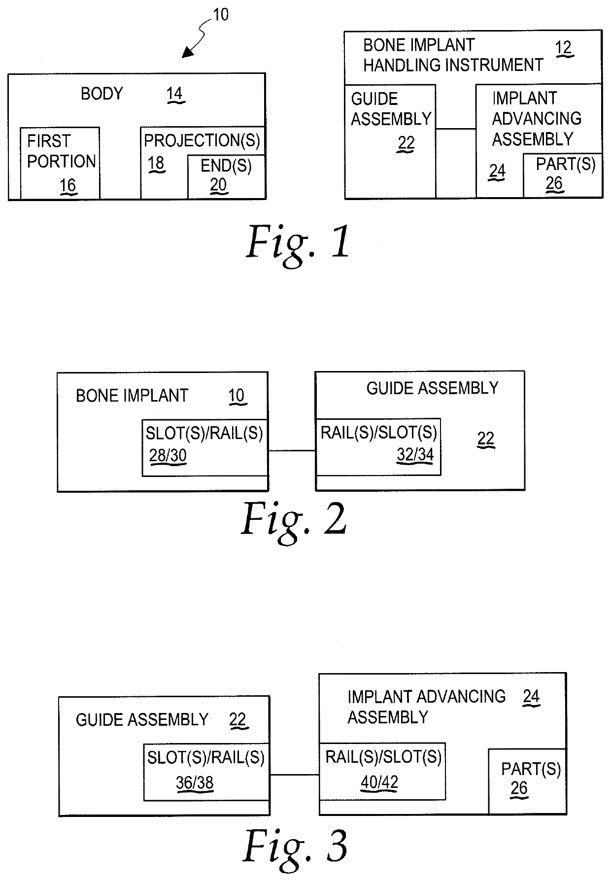
[0075]The present invention is directed to the combination of a bone implant, as shown schematically at 10 in FIG. 1, and a bone implant handling instrument 12, shown also schematically in FIG. 1, usable to place the bone implant 10 in an operative position during a surgical procedure.

[0076]The bone implant 10 has a body 14 with a first portion 16 and at least one projection 18. With the bone implant 10 in an operative position, the first portion 16 overlies an outer bone surface, and the at least one projection 18 extends into at least one bone part.

[0077]The schematic showing of the bone implant 10 is intended to encompass any bone implant that requires the penetration, and purchase, of bone by an integral part thereof, for the bone implant 10 to perform its function, whether it be to facilitate the stabilization of one or more bone fragments, stabilize a major bone fracture, stabilize bone parts during a correction / osteotomy, or otherwise contribute to the mounting of the bone im...


PUM


Abstract

The combination of: a) a bone implant having a body with a first portion that overlies an outer bone surface and first and second projections; and b) a bone implant handling instrument comprising: a guide assembly; and an implant advancing assembly. With a part of the bone implant handling instrument bearing against at least one bone part, the bone implant can be guided by the instrument in substantially a straight line in a first direction, while being maintained in substantially a same orientation with respect to the straight line, between a starting position and an operative position. The implant advancing assembly has at least one part that is movable against the bone implant to advance it into the operative position wherein the first and second projections are advanced into one or more bone parts and the first portion of the body overlies an outer bone surface.

Description

CROSS-REFERENCE TO RELATED APPLICATIONS[0001]This application is a continuation-in-part of U.S. patent application Ser. No. 16 / 875,760, filed May 15, 2020, which claims priority to Provisional Application No. 62 / 848,018, filed May 15, 2019, which are incorporated herein by reference.BACKGROUND OF THE INVENTIONField of the Invention[0002]This invention relates to: a) bone implants and, more particularly, to a bone implant having one or more discrete projections that are advanced into one or more bone parts in placing the bone implant in an operative position; and b) a bone implant handling instrument for placing the bone implant in an operative position.Background Art[0003]Many different types of surgical procedures are performed using bone implants that have projections that are advanced into one or more bone parts in placing the bone implant in an operative position. This bone implant configuration, while having other applications, is commonly used to stabilize bone parts at a frac...

Claims


Application Information

Patent Timeline
Patent Type & Authority Applications(United States)
IPC IPC(8): A61B17/80A61B17/90A61B17/064A61B17/10
CPCA61B17/808A61B17/809A61B17/10A61B17/0642A61B17/90A61B17/8897A61B17/92A61B17/8061
Inventor TELLMAN, LUKAS
Owner TRIMED
Why Eureka
Try Eureka