Binder adapted palette
- Summary
- Abstract
- Description
- Claims
- Application Information
AI Technical Summary
Benefits of technology
Problems solved by technology
Method used
Image
Examples
first embodiment
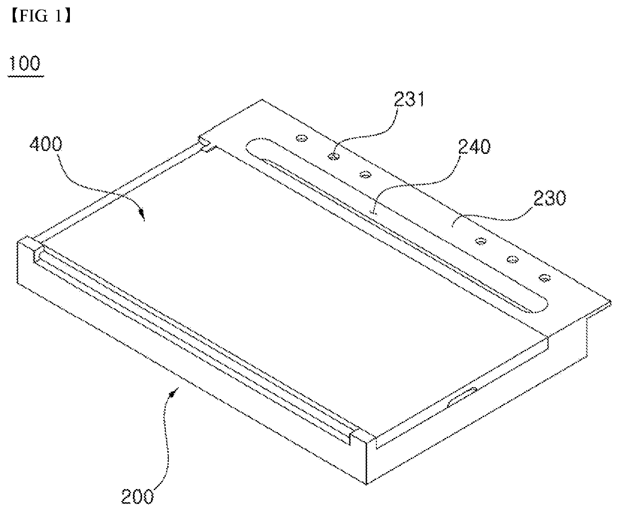
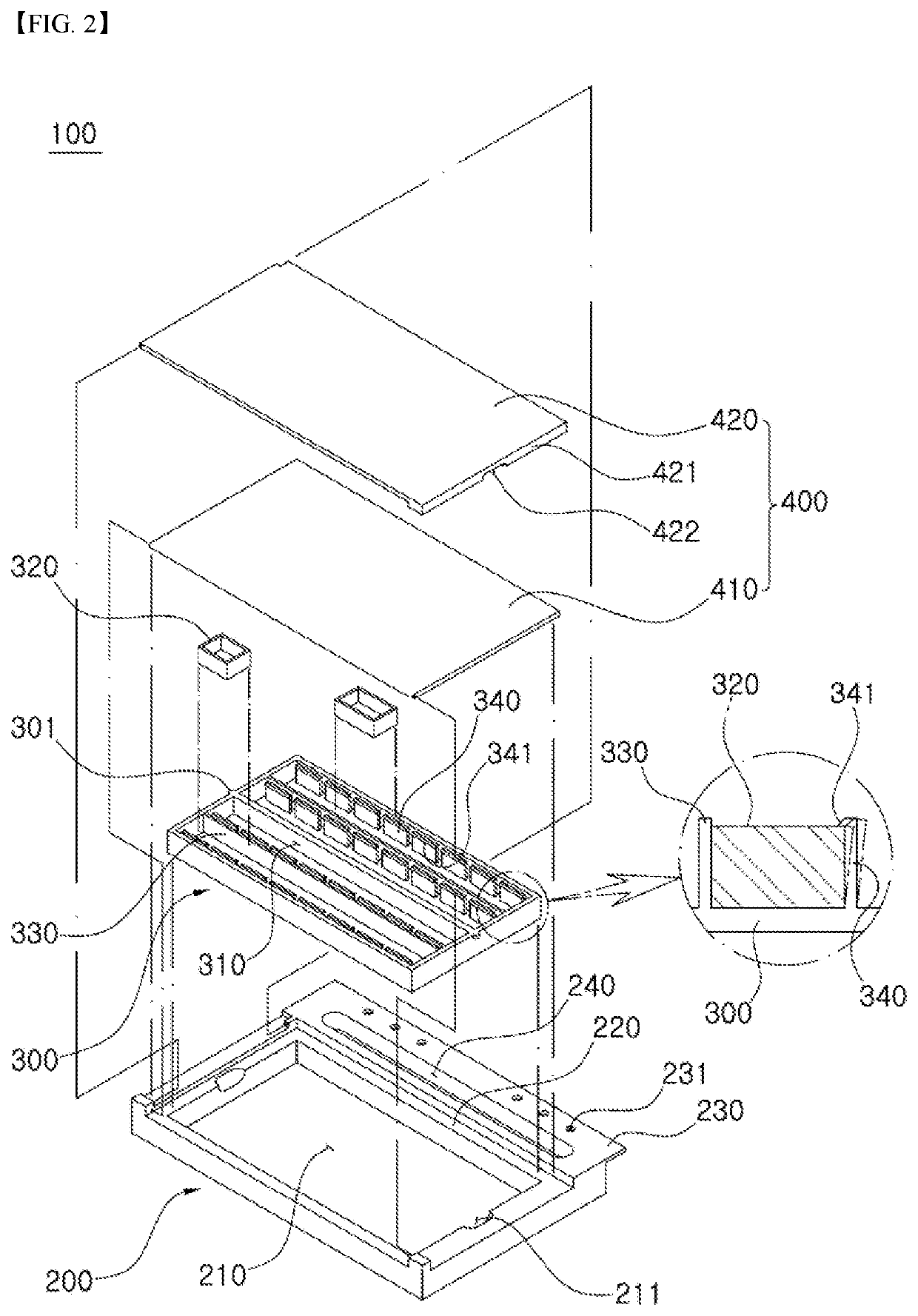
[0034]FIG. 1 is a perspective view of a binder adapted palette according to a first embodiment of the present invention, and FIG. 2 is an exploded perspective view of FIG. 1.
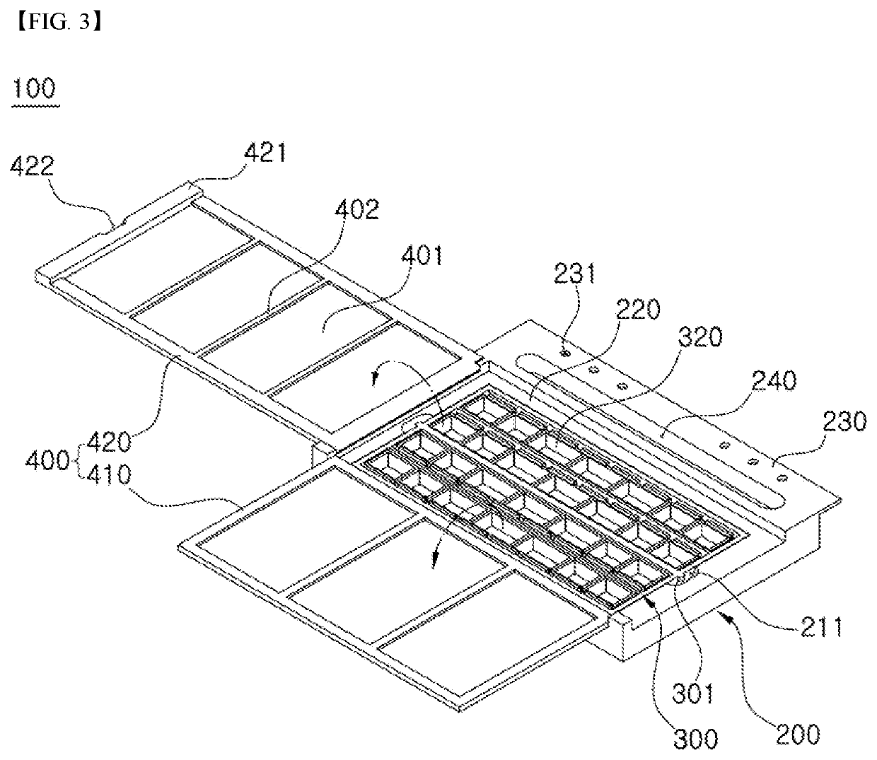
[0035]As shown in FIG. 1 and FIG. 2, a binder adapted palette 100 according to the first embodiment of the present invention includes a body 200 in which the palette accommodation groove 210 is formed, and a palette 300 received in the palette accommodation groove 210 of the body 200, and a cover 400 that opens and closes the palette 300.
[0036]Each of the body 200, the palette 300, and the cover 400 may be made of synthetic resin or metal, or may be made of another material such as wood, if necessary. Further, all of the body 200, the palette 300 and cover 400 may be made of the same material, or at least one thereof may be made of a different material.
[0037]The body 200 accommodates therein the palette 300 and is be coupled to a binder ring 20 (see FIG. 4). Thus, the body 20 together with the binder 10 (see FIG...
second embodiment
[0053]FIG. 5 is an exploded perspective view of a binder adapted palette according to a second embodiment of the present invention.
[0054]A binder adapted palette 100a according to a second embodiment of the present invention has an overall configuration similar to that of the first embodiment as described above in that the former includes a body 200a, a palette 300a, and a cover 400. However, there is a difference therebetween in that the palette 300a is slidably coupled to the palette accommodation groove 210, the paint container 320 is slidably coupled to the palette 300a, and the body 200a includes a storage 250 and a binder portion 230a as detachably interconnected to each other.
[0055]Hereinafter, the same reference numerals will be given to the same components having the same functions as those of the above-described first embodiment, and redundant descriptions thereof will be omitted. The binder adapted palette according to the second embodiment of the present invention will b...
third embodiment
[0067]FIG. 7 is a perspective view of a binder adapted palette according to a third embodiment of the present invention, and FIG. 8 is a diagram of a use state of a binder adapted palette according to the third embodiment of the present invention.
[0068]A binder adapted palette 100b according to the third embodiment of the present invention is similar to the above-described embodiment in that the former includes a body 200b and the cover 400 and is integrally coupled to the binder 10 via the binder ring 20. However, the former has differences from the above-described embodiment in that the body 200b and the palette are integrally formed with each other, and a palette portion 280 and a binder portion 230b are slidably-coupled to each other.
[0069]Hereinafter, the same reference numerals are given to the same components having the same functions as in the above-described embodiment, and duplicate descriptions thereof are omitted. The binder adapted palette 100b according to the third em...
PUM
 Abstract
Description
Claims
Application Information
 - R&D
- Intellectual Property
- Life Sciences
- Materials
- Tech Scout
- Unparalleled Data Quality
- Higher Quality Content
- 60% Fewer Hallucinations
Browse by: Latest US Patents, China's latest patents, Technical Efficacy Thesaurus, Application Domain, Technology Topic, Popular Technical Reports.
© 2025 PatSnap. All rights reserved.Legal|Privacy policy|Modern Slavery Act Transparency Statement|Sitemap|About US| Contact US: help@patsnap.com


