Motorised roller for belt conveyor having high friction in respect of the belt

Active Publication Date: 2018-05-22
COSTR MECCANICHE CRIZAF
View PDF13 Cites 0 Cited by
  • Summary
  • Abstract
  • Description
  • Claims
  • Application Information

AI Technical Summary

Benefits of technology

The present invention provides a motorized roller with no grooves and high adherence to belts, which also shows high resistance to loads. This easy-to-manufacture and economical motorized roller is fitted with a tube or sheath in anti-wear PVC, which enables any type of machining of the roller to be avoided, resulting in considerable saving in production costs. This construction also facilitates the replacement of the abrasive element and makes it more economical, as only the tube fitted on the motorized roller is replaced, rather than the motorized roller itself. The system also improves friction coefficients without modifying the conveyor, without increasing the angle of adherence and without altering the tightener of the belt.

Problems solved by technology

However these types of machining processes of the roller are also expensive.

Method used


Image

  • Motorised roller for belt conveyor having high friction in respect of the belt
  • Motorised roller for belt conveyor having high friction in respect of the belt
  • Motorised roller for belt conveyor having high friction in respect of the belt

Examples


Embodiment Construction

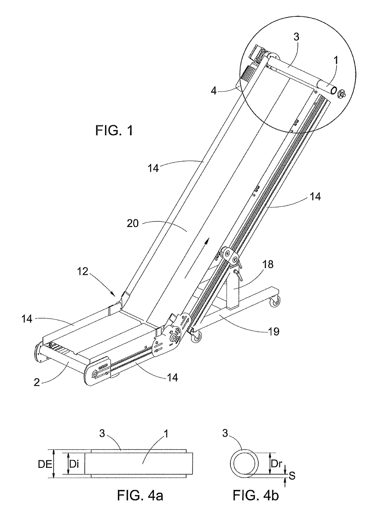
[0020]FIG. 1 illustrates a belt conveyor, denoted overall by reference numeral 100.

[0021]It comprises a frame 12 formed by two opposite shoulders 14 and attached stably to the ground by means of a fixed plinth and uprights 18 (with adjustable height) attached to a base 19 which can be moved by means of wheels.

[0022]Said frame 12 is divided into two adjacent sections defined as a horizontal section (of loading / unloading) and as a sloping transport section.

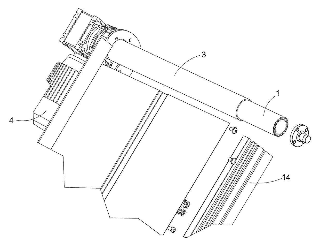
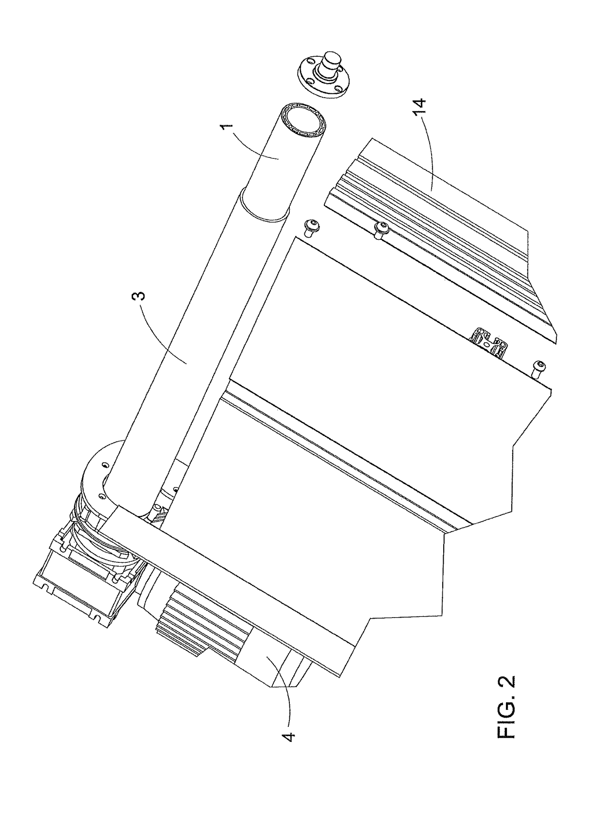
[0023]The frame 12 also comprises a motorized roller or drum 1 rotatably attached to the sloping section at the tail end thereof and a reversing roller or drum 2 rotatably attached to the horizontal section at the head end thereof, said motorized drum 1 and reversing drum 2 being placed between the two opposite shoulders 14.

[0024]A belt 20 which is subtended between the head end of the horizontal section and the tail end of the sloping section is actuated to slide, in the direction of the arrow indicated in FIG. 1, by means of an el...


PUM


Abstract

A motorized or drive roller (1) of a belt conveyor (100) provides, mounted forcedly thereon, an antiwear tube (3) made of PVC additioned with antiwear additives, so that the belt (2) of the belt conveyor (100) rotates around, and in contact with, the antiwear tube (3).

Description

BACKGROUND OF THE INVENTIONField of the Invention[0001]The present invention relates to a motorized roller for a belt conveyor provided with a high traction capability in respect of the belt of the conveyor.[0002]More particularly the present invention relates to such a motorized roller without machining which has high friction in respect of the belt.Description of the Related Art[0003]As is known, belt conveyor are mechanical devices having the function of moving, in a continuous manner, semimanufactured or finished products (placed loose or ordered) along the production lines, for example for the feeding / loading of the products in a production line or for the transfer from one processing station to the next or, again, for the unloading / storage of the finished products.[0004]Belt conveyor are typically made up of a metal framework including the support of the sliding surface of the belt, a drive roller or drive drum (typically the head drum), a reversing idle roller or drum (typica...

Claims


Application Information

Patent Timeline
IPC IPC(8): B65G39/07B65G23/08B65G23/04B65G39/02
CPCB65G39/07B65G23/04B65G39/02B65G23/08B65G2207/48
Inventor CRIBIU', LUCA
Owner COSTR MECCANICHE CRIZAF
Why Eureka
Try Eureka