
Manufacturing method of pixel structure of reflective display

a manufacturing method and reflective display technology, applied in the field of display, can solve the problems of reducing the brightness of the display, affecting the display function, and the inability of human eyes to observe scan patterns or brush patterns, so as to reduce the perception of liquid crystal disturbances, reduce the brightness of the reflected light among the pixels, and improve the display function

Pending Publication Date: 2022-08-25
GIANTPLUS TECH
View PDF2 Cites 0 Cited by
  • Summary
  • Abstract
  • Description
  • Claims
  • Application Information

AI Technical Summary

Benefits of technology

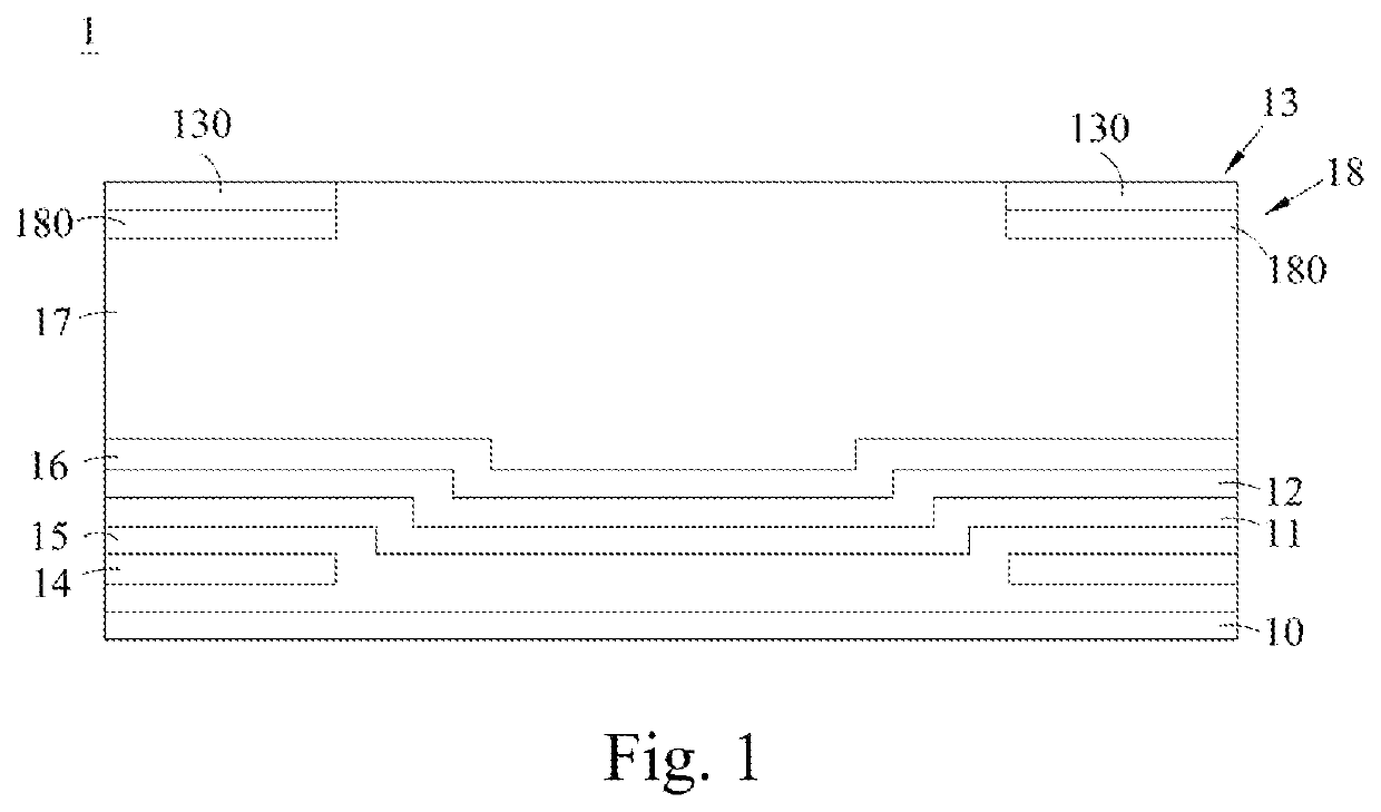
The present invention aims to reduce electrical disturbances and power consumption in a reflective display while maintaining good display function. The shielding layer in the pixel structure shields electrical disturbances and a low reflective layer reduces brightness among pixels, thereby reducing the human eye's perception of liquid crystal disturbances. This results in a more stable and efficient reflective display with improved visual quality.

Problems solved by technology

However, such the driving method may cause some characteristic defects of the display panel to be noticed by human eyes.
Since the perception ability of the human eyes is affected by the refresh rate, in a case of a high refresh rate, the scan patterns or brush patterns are not easily observed by the human eyes.
However, for a reflective display panel, the black matrix also greatly reduces the reflectivity of the entire panel, resulting in decreasing the brightness of the display.

Method used


Image

  • Manufacturing method of pixel structure of reflective display
  • Manufacturing method of pixel structure of reflective display
  • Manufacturing method of pixel structure of reflective display

Examples


Embodiment Construction

[0015]The present disclosure will now be described more fully hereinafter with reference to the accompanying drawings, in which exemplary embodiments of the disclosure are shown. This present disclosure may, however, be embodied in many different forms and should not be construed as limited to the embodiments set forth herein. Rather, these embodiments are provided so that this present disclosure will be thorough and complete, and will fully convey the scope of the present disclosure to those skilled in the art.

[0016]Certain terms are used throughout the description and following claims to refer to particular components. As one skilled in the art will appreciate, manufacturers may refer to a component by different names. This document does not intend to distinguish between components that differ in name but function. In the following description and the claims, the terms “include / including” and “comprise / comprising” are used in an open-ended fashion, and thus should be interpreted a...


PUM

PropertyMeasurementUnit
reflectivityaaaaaaaaaa
frequencyaaaaaaaaaa

Abstract

The present disclosure discloses a manufacturing method of a pixel structure of a reflective display comprising: providing a substrate; forming a shielding layer on the substrate; forming a low reflective layer on the shielding layer; and forming a reflective layer on the low reflective layer, wherein the reflective layer comprises a plurality of reflection regions, the plurality of reflection regions are arranged at intervals, and a part of the low reflective layer is exposed between the plurality of reflection regions. In the present disclosure, the reflection of light in the gap between the pixels is avoided by the low reflective layer, such that the notice of liquid crystal disturbance by human eyes is reduced, and a reflective display with good display function and low power consumption is implemented.

Description

CROSS REFERENCE TO RELATED APPLICATION[0001]This application is a Divisional of Application No. 17 / 083,317, filed Oct. 29, 2020, which claims the priority benefit of Taiwan Patent Application Number 109213003, filed on Sep. 30, 2020, the full disclosure of which is incorporated herein by reference.BACKGROUNDTechnical Field[0002]The present disclosure relates to the technical field of a display, particularly to a manufacturing method of a pixel structure of a reflective display.Related Art[0003]Electronic products are widely used in daily life with the advancement of science and technology; therefore, the reliance on electronic products for people increases. In order to use electronic products anytime and anywhere, these electronic products are developed toward the trend of being lighter, thinner, shorter, and smaller, so that users can carry these electronic products with them.[0004]For thin and light portable electronic products, in addition to having a good display function, the d...

Claims


Application Information

Patent Timeline
Patent Type & Authority Applications(United States)
IPC IPC(8): H01L27/12
CPCH01L27/1218H01L27/1288H01L27/1262H01L27/124
Inventor JIANG, I-TAWU, CHE-YAOCHOU, KAI-JU
Owner GIANTPLUS TECH
Learn More