Vibration damping device and method of manufacturing vibration damping device

a technology of vibration damping and damping device, which is applied in the manufacture of springs/dampers, rubber-like material springs, and springs/dampers design characteristics, etc., and can solve the problems of time-consuming deburring work, increase in assembly accuracy and cost,

Pending Publication Date: 2022-09-08
SUMITOMO RIKO CO LTD
View PDF0 Cites 0 Cited by
  • Summary
  • Abstract
  • Description
  • Claims
  • Application Information

AI Technical Summary

Problems solved by technology

This may entail problems in assembly accuracy and cost increase, namely, an assembly defect, a time-consuming deburring work, and the like.

Method used


Image

  • Vibration damping device and method of manufacturing vibration damping device
  • Vibration damping device and method of manufacturing vibration damping device
  • Vibration damping device and method of manufacturing vibration damping device

Examples


Embodiment Construction

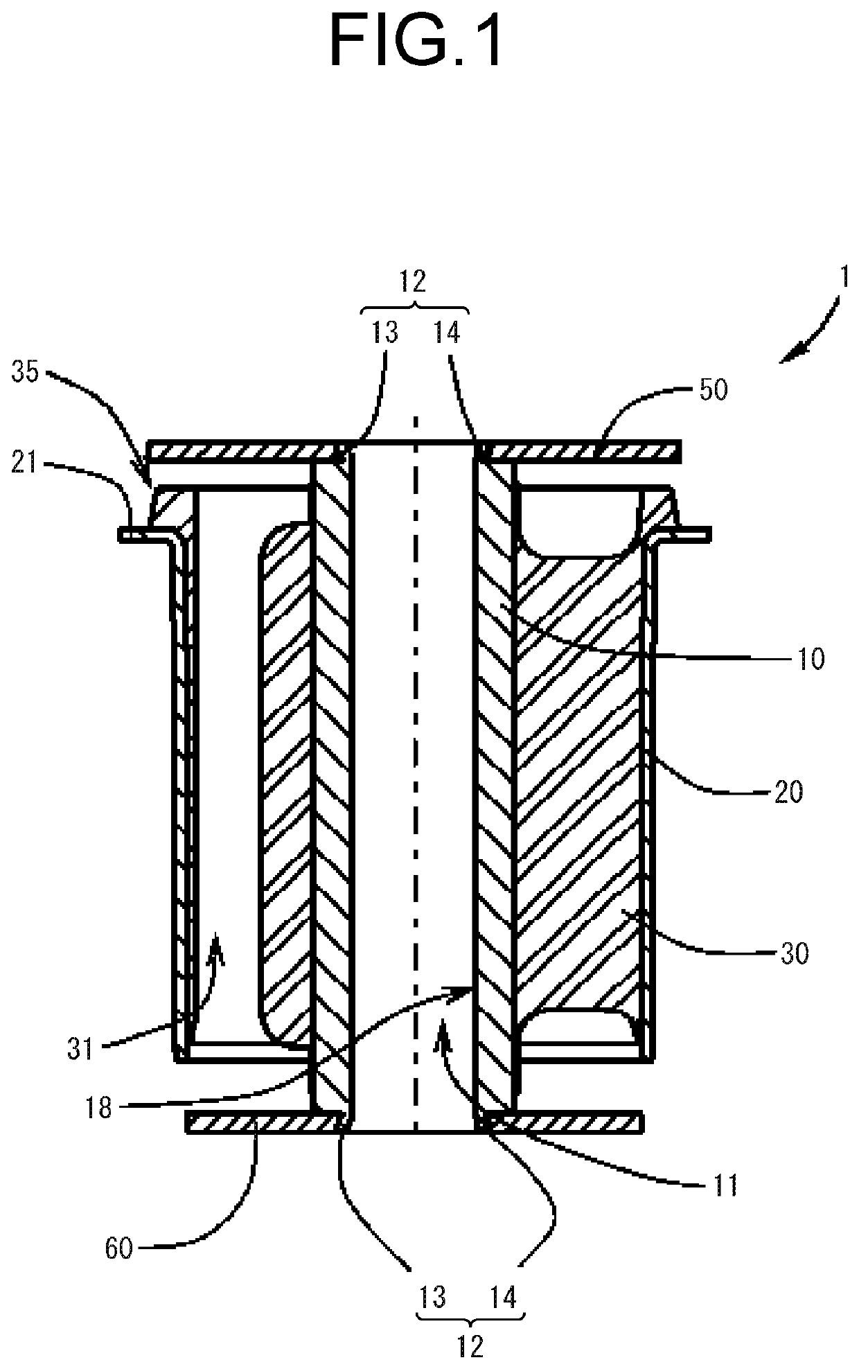
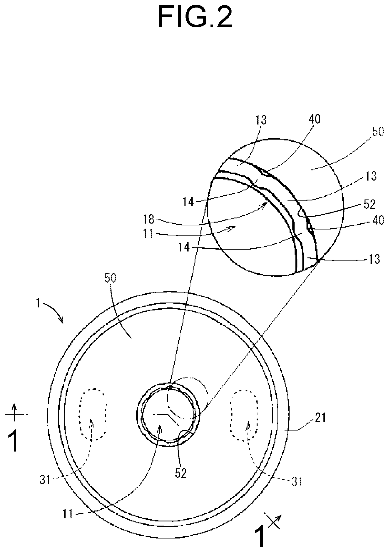
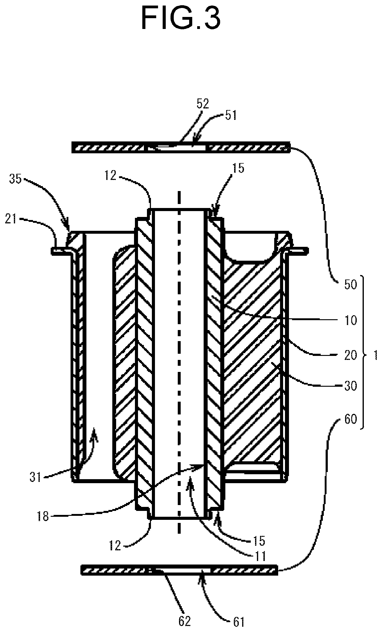
[0047]Hereinafter, practical embodiments of the present invention will be described with reference to the drawings. First, the structure of the vibration damping device which is the target of the present invention will be described. In the description hereinbelow, the vertical direction and the axial direction refer to the vertical direction in FIG. 1.

[0048]A vibration damping device 1 according to a first practical embodiment is configured to be attached, for example, between a vibration source (not shown) and a vehicle body frame (vehicle body) provided in an automobile.

[0049]FIG. 1 is a cross-sectional view schematically showing an example of the vibration damping device 1 according to the present practical embodiment. As shown in FIG. 1, the vibration damping device 1 includes an inner 10 of round tubular shape, an outer 20 of round tubular shape disposed concentrically with the inner 10 and disposed on the radially outer side of the inner 10, an elastic body 30 arranged between...


PUM


Abstract

A vibration damping device including an inner, a tubular outer disposed on a radially outer side of the inner, an elastic body connecting the inner and the outer, and a retainer disposed on at least one axial end of the inner and penetrated by an opening in an axial direction. The inner includes an annular projection extending outward in the axial direction from at least one axial end face of the inner and inserted in the opening of the retainer. The annular projection includes a plurality of compressed fixation parts arranged apart from each other in a circumferential direction. The retainer is fixed by compression to the inner by the compressed fixation parts being compressed against an inner circumferential surface of the opening.

Description

INCORPORATED BY REFERENCE[0001]The disclosures of Japanese Patent Application Nos. 2021-034884 filed on Mar. 5, 2021 and 2021-126654 filed on Aug. 2, 2021, each including the specification, drawings and abstract is incorporated herein by reference in its entirety.BACKGROUND OF THE INVENTION1. Field of the Invention[0002]The present invention relates to a vibration damping device and a method of manufacturing the vibration damping device.2. Description of the Related Art[0003]Conventionally, as a vibration damping device, there is known a bushing assembly including an outer tube, an inner tube, a main rubber linking the inner circumferential surface of the outer tube and the outer circumferential surface of the inner tube, and retainers arranged at opposite axial ends of the inner tube, in which the retainers have a compression part fixed at the end of the inner tube. For example, Japanese Unexamined Utility Model Publication No. JP-U-S60-122035 describes such a bushing assembly.SUMM...

Claims


Application Information

Patent Timeline
Patent Type & Authority Applications(United States)
IPC IPC(8): F16F1/38F16F1/373F16F1/387
CPCF16F1/3842F16F1/3735F16F1/3873F16F2226/045F16F2230/0005F16F2234/02F16F1/3814F16F1/3828
Inventor HOTTA, KAZUKI
Owner SUMITOMO RIKO CO LTD
Why Eureka
Try Eureka