
Plate-shaped workpiece processing method including first and second cutting steps, where the second step includes use of a cutting fluid containing an organic acid and an oxidizing agent

a workpiece and processing method technology, applied in the field of plate-shaped workpiece processing methods, can solve the problems of difficult to increase the feed speed, increase the degree of burrs or dragging, and so as to reduce the thickness of the workpiece to be cut in each step, reduce the ductility of metal, and increase the processing speed

Active Publication Date: 2020-05-26
DISCO CORP
View PDF29 Cites 0 Cited by
  • Summary
  • Abstract
  • Description
  • Claims
  • Application Information

AI Technical Summary

Benefits of technology

The present invention provides a method for processing a plate-shaped workpiece with a division line and metal member. The method involves a two-step cutting process using two cutting blades, resulting in faster processing as compared to fully cutting the workpiece in one step. In the second cutting step, a cutting fluid containing an organic acid and an oxidizing agent is supplied to the workpiece, modifying the metal to suppress burrs and improve workability without losing ductility. This results in easier and more efficient processing of plate-shaped workpieces.

Problems solved by technology

On the other hand, when the metal member formed on the workpiece is cut by a cutting blade, the cutting blade may be clogged as described above and there also arises another problem such that the metal member cut by the cutting blade is elongated, causing the generation of burrs or the occurrence of dragging.
In general, when a feed speed is increased, a cutting load is increased and a processing heat generated in cutting the workpiece is increased, resulting in an increase in degree of burrs or dragging.
Accordingly, it is difficult to increase the feed speed from the viewpoint of prevention of a degradation in processing quality.
Moreover, the film property on the surface of the metal member is changed by the oxidizing agent contained in the cutting fluid, so that the ductility of the metal member is lost to cause easy cutting, thereby improving the workability.

Method used


Image

  • Plate-shaped workpiece processing method including first and second cutting steps, where the second step includes use of a cutting fluid containing an organic acid and an oxidizing agent
  • Plate-shaped workpiece processing method including first and second cutting steps, where the second step includes use of a cutting fluid containing an organic acid and an oxidizing agent
  • Plate-shaped workpiece processing method including first and second cutting steps, where the second step includes use of a cutting fluid containing an organic acid and an oxidizing agent

Examples


Embodiment Construction

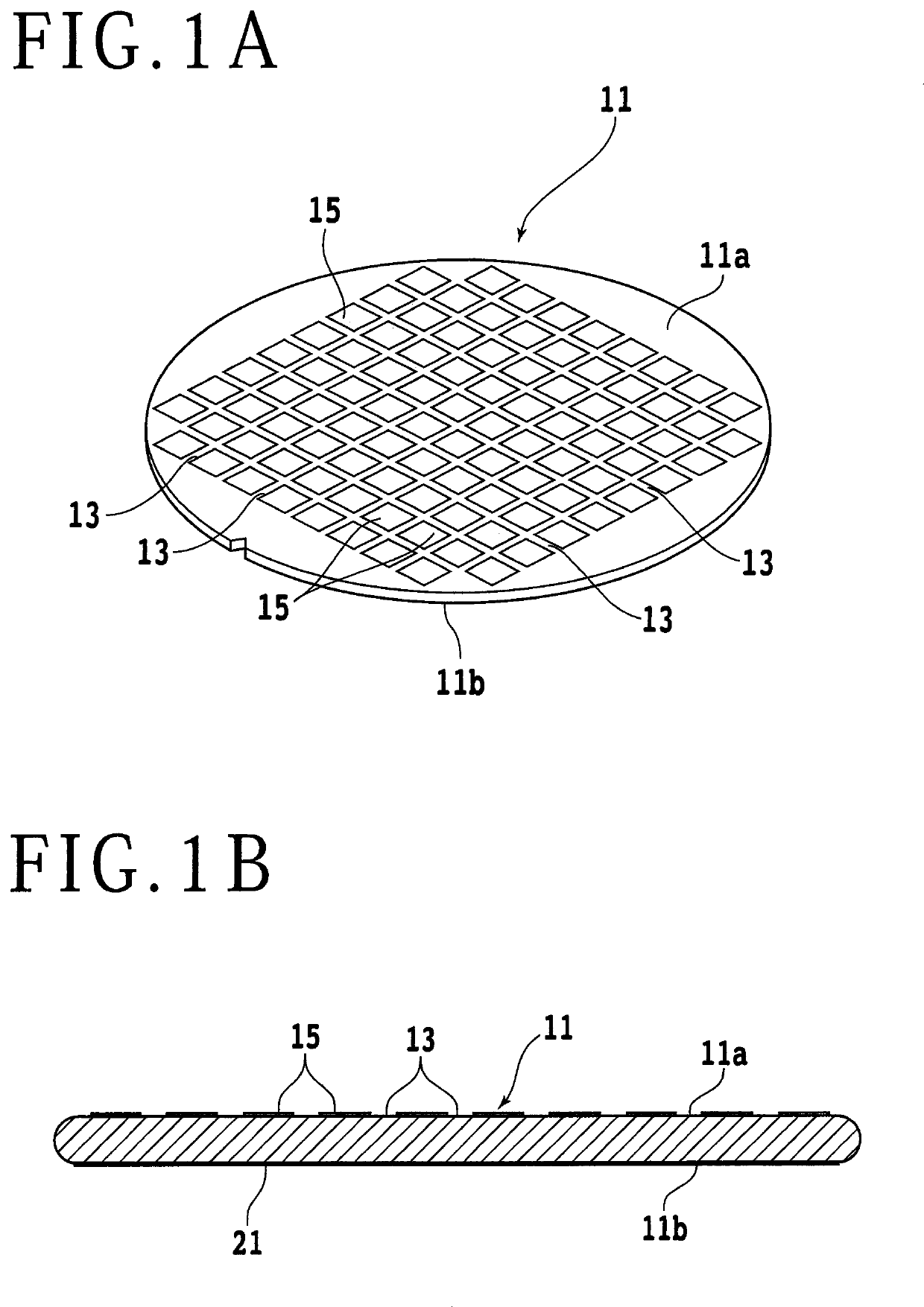
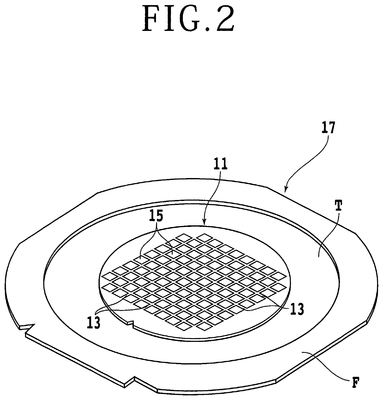
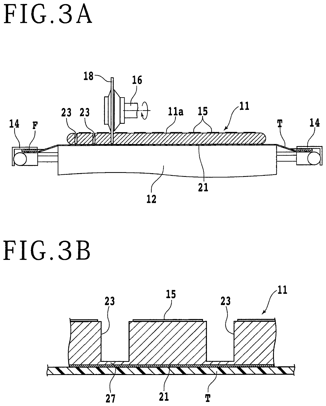
[0017]Preferred embodiments of the present invention will now be described in detail with reference to the drawings. Referring to FIG. 1A, there is shown a perspective view of a semiconductor wafer (which will be hereinafter sometimes referred to simply as wafer) 11. As shown in FIG. 1A, the semiconductor wafer 11 has a front side 11a and a back side 11b. In FIG. 1A, the front side 11a of the semiconductor wafer 11 is shown. FIG. 1B is a sectional view of the semiconductor wafer 11. A plurality of crossing division lines 13 are formed on the front side 11a of the wafer 11 to thereby define a plurality of separate regions where a plurality of devices 15 such as LSIs (Large Scale Integrated Circuits) are formed. More specifically, the plural crossing division lines 13 are composed of a plurality of parallel division lines extending in a first direction and a plurality of parallel division lines extending in a second direction perpendicular to the first direction. As shown in FIG. 1B, ...


PUM

PropertyMeasurementUnit
thicknessaaaaaaaaaa
thicknessaaaaaaaaaa
thicknessaaaaaaaaaa

Abstract

A method for processing a plate-shaped workpiece having a division line and a metal member formed on the division line or in an area corresponding to the division line includes a holding step of holding the workpiece on a chuck table with the metal member oriented downward, a first cutting step of cutting the workpiece along the division line by using a first cutting blade, thereby forming a first cut groove having a bottom not reaching the metal member, and a second cutting step of cutting the workpiece along the first cut groove by using a second cutting blade, thereby forming a second cut groove fully cutting the workpiece along the division line so as to divide the metal member. The second cutting step includes supplying a cutting fluid containing an organic acid and an oxidizing agent to the workpiece.

Description

BACKGROUND OF THE INVENTIONField of the Invention[0001]The present invention relates to a plate-shaped workpiece processing method for processing a plate-shaped workpiece having a division line and a metal member formed on the division line or in an area corresponding to the division line.Description of the Related Art[0002]A wafer such as a semiconductor wafer has a front side on which a plurality of devices are formed so as to be separated by a plurality of crossing division lines. The wafer thus having the devices is cut along the division lines and thereby divided into individual device chips. There is a case that a metal film is formed on the back side of the wafer, so as to improve the electrical characteristics of each device. However, when the metal film is cut by a cutting blade, the cutting blade may be clogged. Furthermore, when the wafer is cut by this cutting blade clogged, there arises a problem such that cracking may occur in the wafer or the cutting blade may be dama...

Claims


Application Information

Patent Timeline
Patent Type & Authority Patents(United States)
IPC IPC(8): H01L21/67H01L21/78H01L21/304H01L21/683H01L21/687
CPCH01L21/67092H01L21/78H01L21/3043H01L21/6836H01L21/68714H01L2221/68327H01L21/76
Inventor TAKENOUCHI, KENJI
Owner DISCO CORP
Learn More