
Rapidly assembled tabletop support

a tabletop support and assembly technology, applied in the direction of furniture joining parts, adjustable height tables, fastening means, etc., can solve the problems of reducing production efficiency, increasing the manufacturing cost, and cumbersome installation methods of existing tabletop supports in the mark

Active Publication Date: 2022-09-29
CHANGZHOU KAIDI ELECTRICAL INC
View PDF24 Cites 0 Cited by
  • Summary
  • Abstract
  • Description
  • Claims
  • Application Information

AI Technical Summary

Benefits of technology

The present invention provides a rapidly assembled tabletop support that is efficient, simple, and easy to install and use. It consists of cross members and a stringer that is perpendicular to the cross members. The stringer has steps and a neck where a locking mechanism is engaged. The stringer is pushed to match the steps with the cross member, and the locking mechanism is engaged with the neck of the stringer, allowing for quick assembly. The stringer is an integral part of the stringer, eliminating the need for welding, which increases production efficiency and simplifies the structure. The cross members can adjust the spacing in a large range to adjust the length of the tabletop support with the aid of connecting rods.

Problems solved by technology

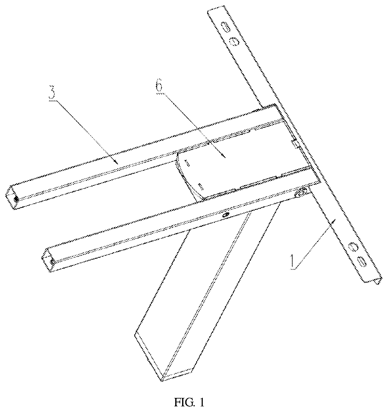
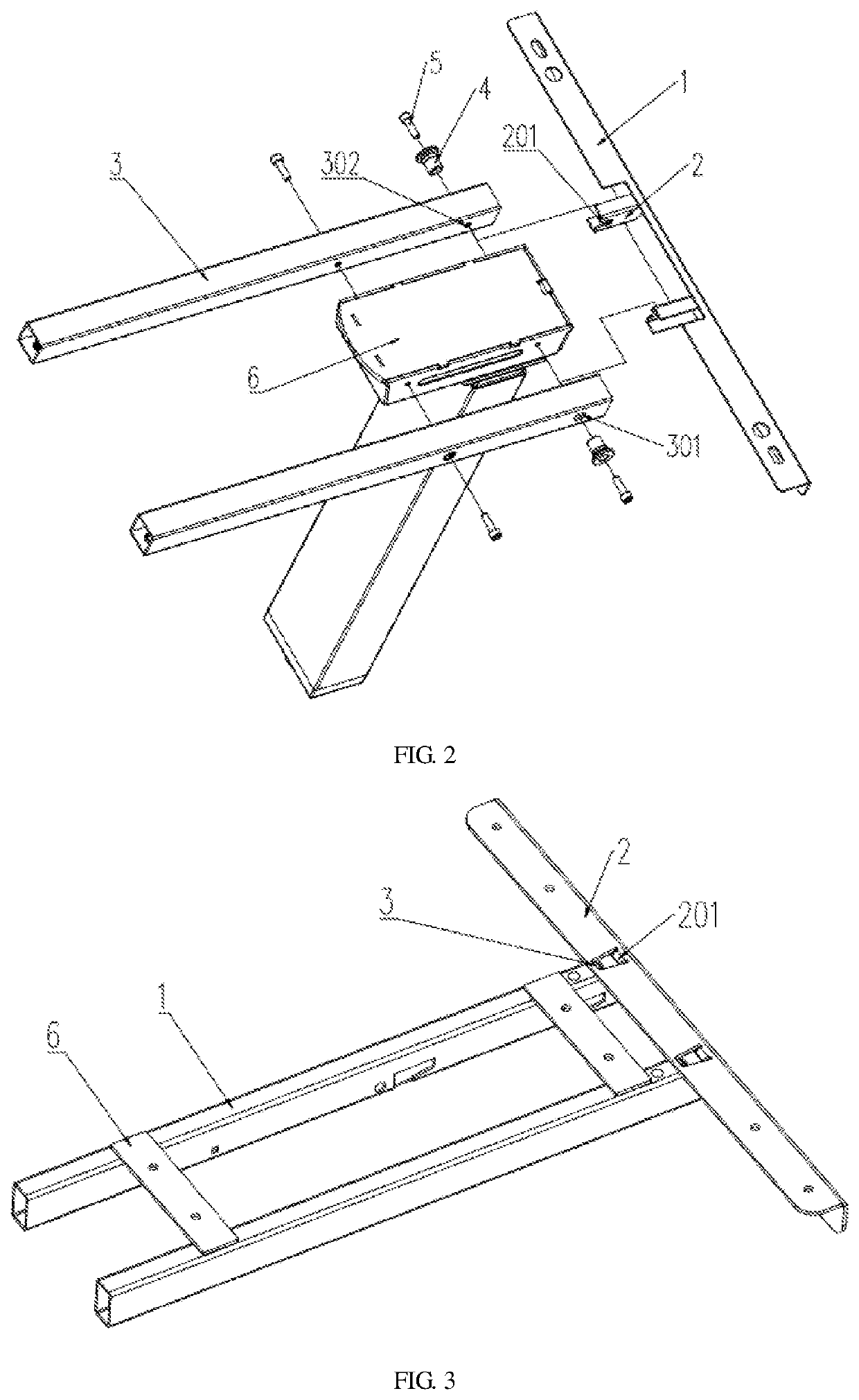
However, the installation methods of existing tabletop supports in the market are generally cumbersome, as shown in FIG. 1 and FIG. 2.
However, the slot 2 needs to be welded on the stringer assembly 1, which increases the fabricating cost and reduces the production efficiency.
At the same time, the screw needs to be locked when assembling, showing low assembly efficiency.

Method used


Image

  • Rapidly assembled tabletop support
  • Rapidly assembled tabletop support
  • Rapidly assembled tabletop support

Examples


embodiment 1

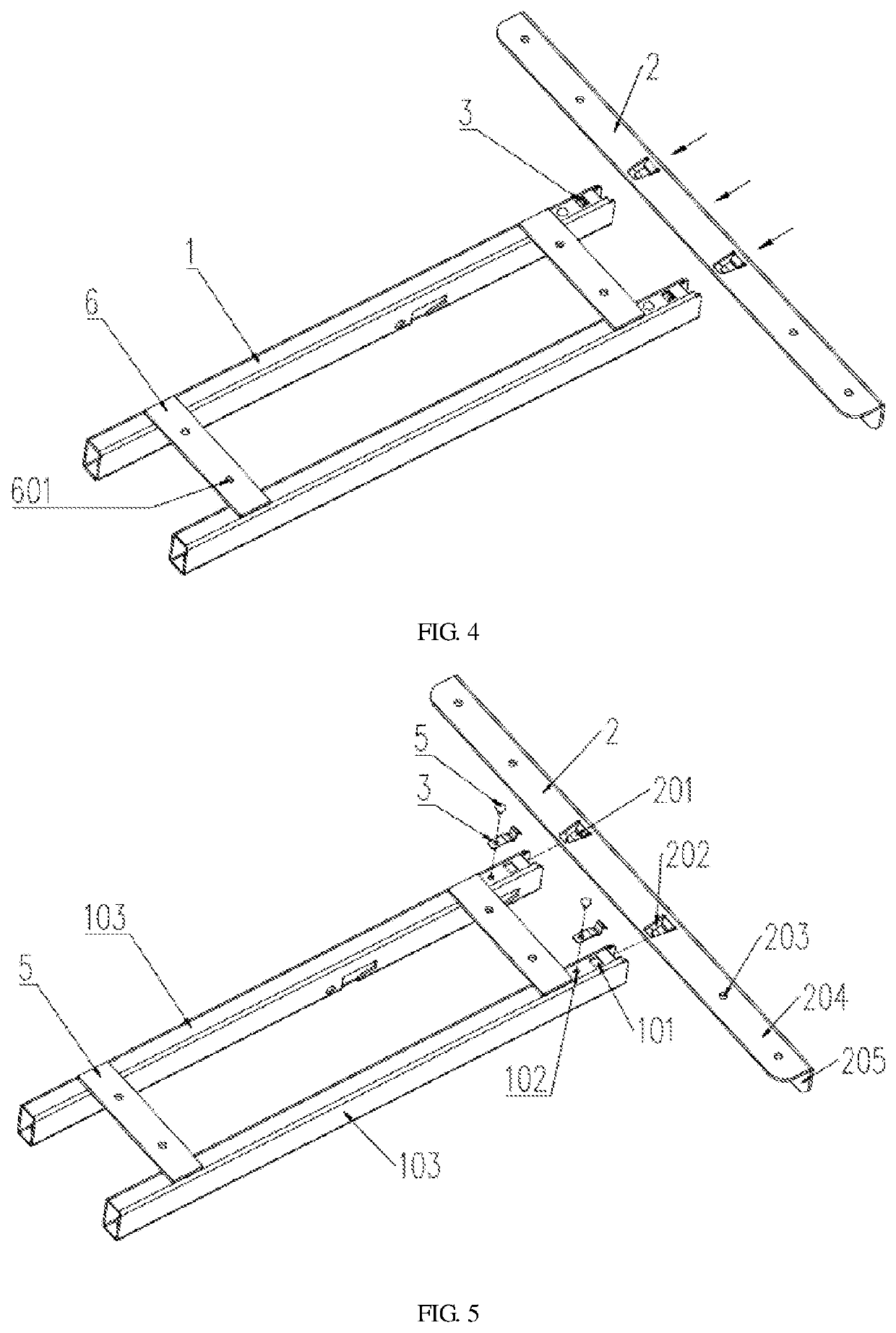
[0034]See FIG. 3-FIG. 7 for a rapidly assembled tabletop support of the present invention. With suitable tabletop plates, it forms dining tables, desks, office tables, conference tables, student desks, or coffee tables and comprises the cross member 1 and the stringer 2 perpendicular to the cross member 1.

[0035]The locking mechanism 3 is fixed on the cross member 1 and is the spring piece. The cross member 1 is provided with the first through-hole 101 for the locking mechanism 3 to eject. The locking mechanism 3 is made of spring steel and composed of the connecting section 301 and the folding section 302. The connecting section 301 and the folding section 302 are of an integrated structure. The locking mechanism 3 is connected to the cross member 1 through the connecting section 301. The folding section 302 has the ejection part which includes the peak part 3022 and the guide part 3021 connected end to end and is ejected from the first through-hole 101 under the guidance of the gui...

embodiment 2

[0046]See FIG. 8. Compared with Embodiment 1, Embodiment 2 has the following differences: The locking mechanism 3 is integrated with the cross member 1 and is a part of the cross member 1, and specifically, the locking mechanism 3 is formed by the pressing of the cross member 1.

embodiment 3

[0047]See FIG. 9-FIG. 10. Compared with Embodiment 1, Embodiment 3 has the following differences: there are two cross members 1 which are arranged along the length direction of the tabletop support and symmetrically distributed left and right, and there are two connecting rods 4 inside the two cross members 1 which are respectively fixed with the corresponding ends of the connecting rods 4 after the distance between the two cross members 1 is determined, realizing the adjustable length of the tabletop support.


PUM


Abstract

The present invention claims a rapidly assembled tabletop support, comprising cross members and a stringer perpendicular to the cross members. There are locking mechanisms on the cross member and steps and necks corresponding to the steps on the stringer. By pushing the stringer to move relative to the cross member, the stringer and its steps are closely matched with the tube wall of the cross member, and the locking mechanism is engaged into the neck on the stringer, realizing rapid engagement between the cross member and the stringer. The rapidly assembled tabletop support is characterized by high production efficiency, simple structure, convenient installation, reliable use, and adjustable length.

Description

CROSS REFERENCE TO RELATED APPLICATION[0001]This application claims the priority of Chinese Patent Application No. 202010325411.3, entitled “Rapidly Assembled Tabletop Support”, filed on Apr. 23, 2020, the disclosure of which is incorporated herein by reference in its entirety.BACKGROUND OF THE INVENTION1. Field of the Invention[0002]The present invention belongs to the technical field of intelligent lifting tables, specifically relating to a rapidly assembled tabletop support.2. Description of Related Art[0003]As we all know, tables play a very important role in daily life, and people need them all the time. However, the installation methods of existing tabletop supports in the market are generally cumbersome, as shown in FIG. 1 and FIG. 2. The stringer assembly 1 has a slot 2 which is provided with a mounting hole 201. The cross member 3 is provided with a through-hole 301 and a threaded hole 302 which correspond to the mounting hole 201. The cross member 3 is installed outside th...

Claims


Application Information

Patent Timeline
Patent Type & Authority Applications(United States)
IPC IPC(8): A47B13/00A47B9/00
CPCA47B13/003A47B9/00A47B2230/0037A47B13/06A47B2200/0012F16B12/38A47B2013/006
Inventor ZHU, GENGXING
Owner CHANGZHOU KAIDI ELECTRICAL INC
Learn More