Scavenging pump

a technology of scavenging pump and oil pump, which is applied in the direction of mechanical equipment, machines/engines, pressure lubrication, etc., can solve the problems of large air gap between the gears for drawing oil, reduced sealing performance, and difficulty in drawing sufficient oil for such a pump to achieve the effect of efficient oil circulation

Inactive Publication Date: 2022-09-29
YAMADA SEISAKUSHO KK
View PDF2 Cites 0 Cited by
  • Summary
  • Abstract
  • Description
  • Claims
  • Application Information

AI Technical Summary

Benefits of technology

[0010]According to the present disclosure, a scavengin

Problems solved by technology

Even if the scavenging pump is operated in such a state, a large amount of air is present between gears for drawing the oils.
When the oils filled

Method used


Image

  • Scavenging pump
  • Scavenging pump
  • Scavenging pump

Examples


embodiment

[0017][Embodiment]

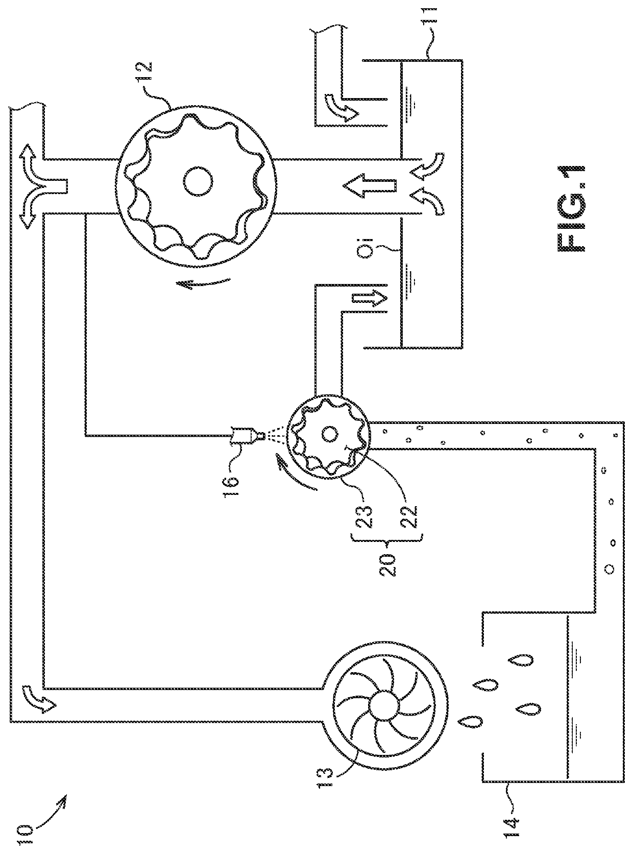
[0018]With reference to FIG. 1, for example, a vehicle is provided with an oil circulating device 10 for circulating oils. A scavenging pump 20 according to the present disclosure forms a part of the oil circulating device 10.

[0019]The oil circulating device 10 includes an oil pan 11 that reserves therein oils Oi, a feed pump 12 that can draw the oils Oi from the oil pan 11, a catch tank 14 that collects the oils Oi which are fed to a turbocharger 13 from the feed pump 12, and which cool the turbocharger 13, a scavenging pump 20 that draws the oils Oi from the catch tank 14 to the oil pan 11, and a nozzle 16 that can inject the oils Oi to the scavenging pump 20.

[0020]The flow channel of the oil circulating device 10 is branched in order to lubricate other various components to operate and to cool those in addition to the turbocharger 13. The oils Oi that pass through the other components are also returned to the oil pan 11.

[0021]In this example, the components whic...


PUM


Abstract

A scavenging pump is utilized to draw oils from a catch tank that collects the oils supplied to components to an oil pan that reserves therein the oils. The scavenging pump includes gears to draw the oils, and a housing that stores therein the gears. An oil receiving portion capable of receiving the oils injected from the exterior is formed in an outer circumferential surface of the housing, and an oil introducing hole that introduces the oils injected to the oil receiving portion into the interior is opened at a position continuous from a lower part of the oil receiving portion and facing the gears.

Description

FIELD OF THE INVENTION[0001]The present disclosure relates to a scavenging pump that draws oils from a catch tank which collects the oils supplied to components to an oil pan which reserves therein the oils.BACKGROUND[0002]Some vehicles are provided with components, such as a turbocharger. Such components are allowed to operate and are cooled by lubrication oils that circulate within a vehicle. Oils that pass through a component are collected by a catch tank, and are returned to an oil pan from the catch tank. At this time, when the catch tank is located at a lower site than that of the catch tank, oils are drawn from the catch tank to the oil pan using a scavenging pump. JP 2019-78190 A discloses a conventional technology related to such a scavenging pump.[0003]JP 2019-78190 A describes the features of a scavenging pump by a comparison with a feed pump for circulating oils. One of such features is that, although a feed pump carries substantially oils only, a scavenging pump carries...

Claims


Application Information

Patent Timeline
IPC IPC(8): F01M1/02
CPCF01M1/02F01M2001/0238F01M2011/0095
Inventor FUJII, MASAHIKOHIRAYAMA, YUUKAWASHIMA, KENJIMASUDA, MASAKOKANEKO, ATSUSHI
Owner YAMADA SEISAKUSHO KK
Why Eureka
Try Eureka