Remote driving device and operation mechanism for work machine

a technology of driving device and operation mechanism, which is applied in the direction of mechanical control device, manual control with single controlling member, instruments, etc., can solve the problems of link mechanism not being able to make a compact circumference of the operation lever, the length of the operation link mechanism in the rotary shaft direction is increased by a thickness of the angle detector, and the link mechanism might interfere with the sea

Pending Publication Date: 2022-10-06
KOBELCO CONSTR MASCH CO LTD
View PDF0 Cites 0 Cited by
  • Summary
  • Abstract
  • Description
  • Claims
  • Application Information

AI Technical Summary

Benefits of technology

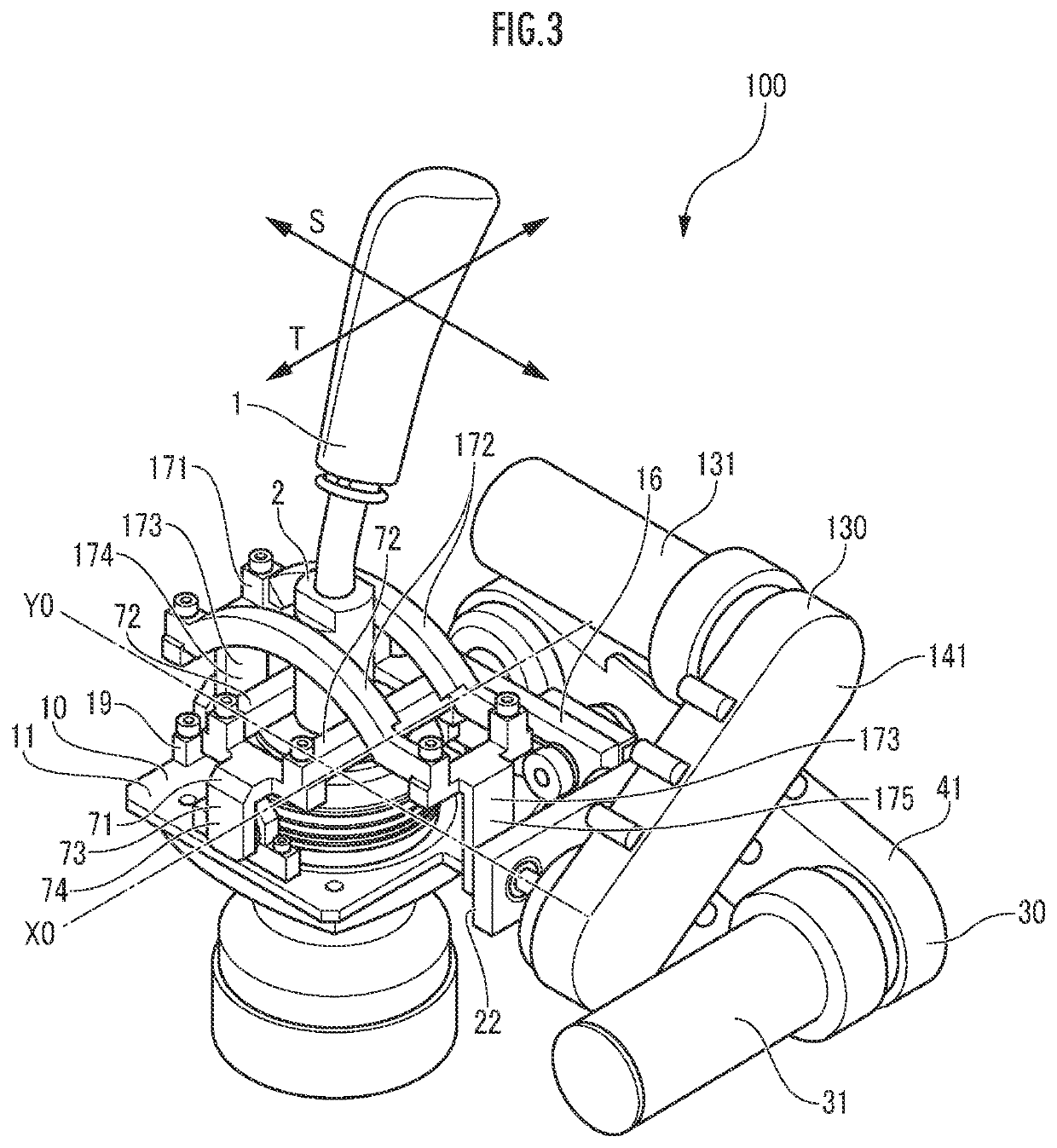
The remote driving device can detect how tilted the operation lever is through a component on the first drive shaft. This means that space on the drive shaft doesn't need to be reserved for wires and such connections, which results in a smaller device. Additionally, the device is designed so that the gap between the operation lever and the guide members remains consistent, regardless of which operation lever is used. This ensures consistent operation with the guide members.

Problems solved by technology

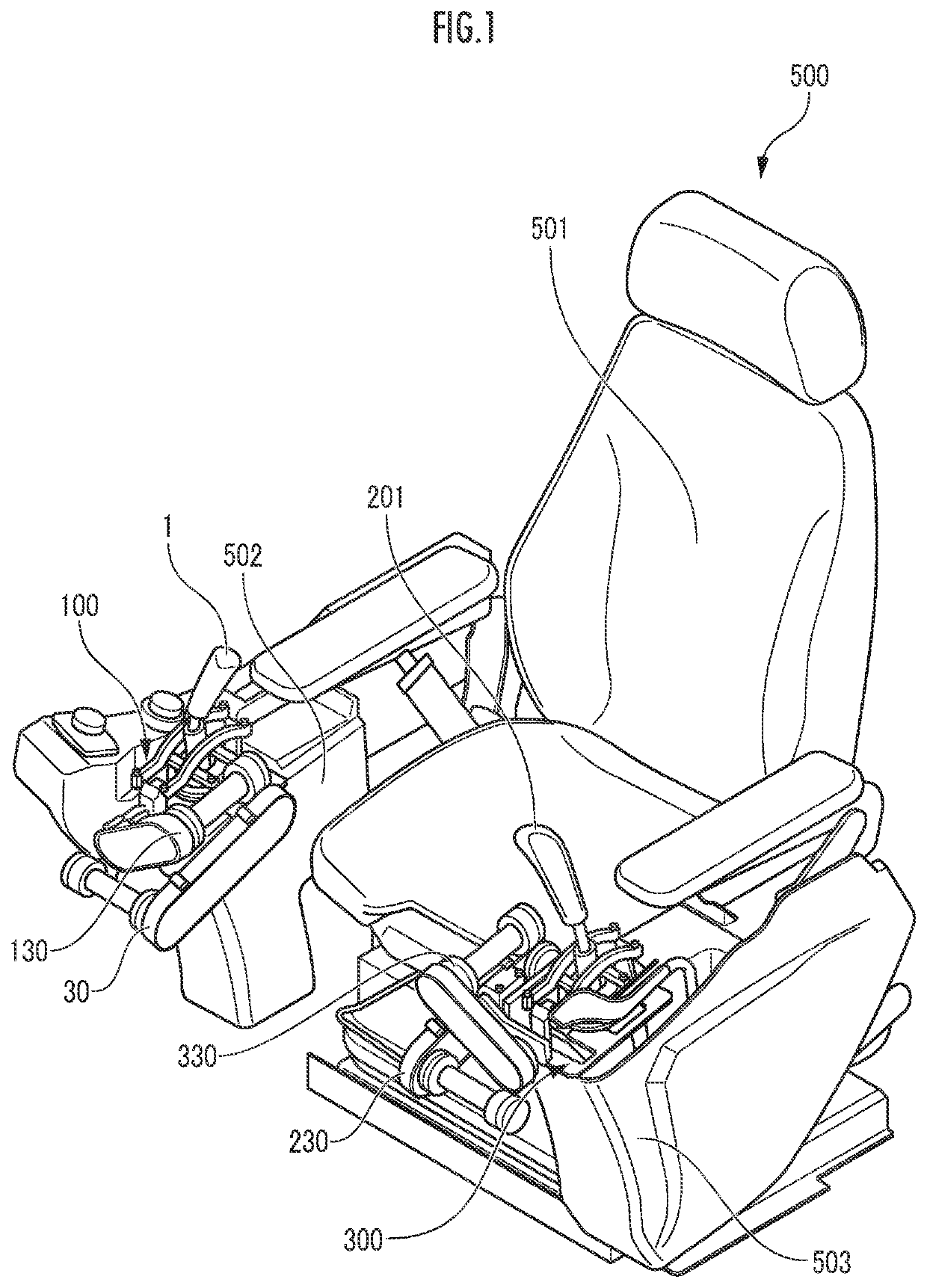
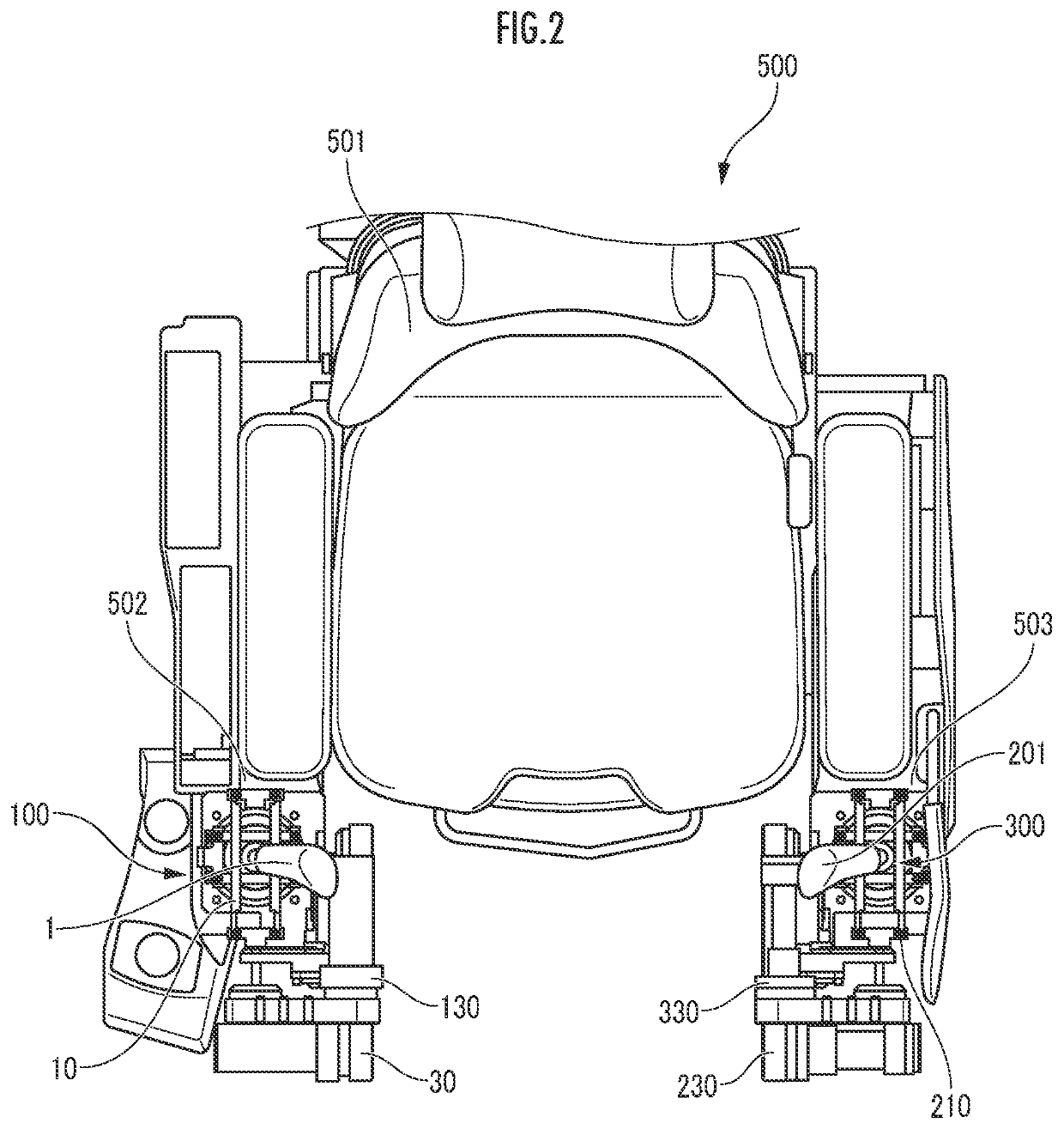
In such a remote driving device as described in Japanese Patent Laid-Open No. 11-50493, the operation link mechanism is retrofitted in the operation lever of the vehicle, and hence with a combination of the vehicle and the operation link mechanism, the operation link mechanism might interfere with a seat, an operation device or the like which is placed in the vehicle.
Furthermore, in a case where an actual driving amount of the operation lever by a remote operation is to be detected, since the angle detector is attached to one end of a rotary shaft of the operation link mechanism, a length of the operation link mechanism in a rotary shaft direction increases by a thickness of the angle detector, which makes it difficult to make a circumference of the operation lever compact.
However, when arranging the pair of guide members as close to each other as possible to design the circumference of the operation lever compact, the operation lever might interfere with the guide members.
Also, when an interval between the pair of guide members is increased to prevent the operation lever from being interfered with the guide members, responsiveness of the operation lever might deteriorate.

Method used


Image

  • Remote driving device and operation mechanism for work machine
  • Remote driving device and operation mechanism for work machine
  • Remote driving device and operation mechanism for work machine

Examples


first embodiment

[0187]In a first embodiment, as shown in FIGS. 20A and 20B, a protrusion 674d protruding downward from a bottom surface is formed in a portion of the front end 674a of each of the pair of first guide members 674 which is close to the other front end 674a in the left-right direction (X-direction) (on an inner side in the left-right direction). Each protrusion 674d is formed to be flat in the side surface on a side away from the other front end 674a in the left-right direction (X-direction) (on an outer side in the left-right direction).

[0188]Furthermore, a concave portion 675b is formed in a middle portion of the front first rotation member 675 in the left-right direction. The concave portion 675b is formed by a bottom surface which has a lower height than a top surface of the first rotation member 675 and is formed by a horizontal surface, and a pair of side surfaces each of which connects the top surface of the first rotation member 675 and an end of the bottom surface in a width d...

second embodiment

[0192]In a second embodiment, as shown in FIGS. 21A and 21B, a protrusion 674e protruding downward from a bottom surface is formed in a portion of a front end 674a of one of a pair of first guide members 674 which is away from a front end 674a of the other first guide member in a left-right direction (X-direction) (on an outer side in the left-right direction). Each protrusion 674e formed to be flat in the side surface on a side closer to the other front end 674a in the left-right direction (X-direction) (on an inner side in the left-right direction). Further, a convex portion 675c is formed in a middle portion of a front first rotation member 675 in the left-right direction. The convex portion 675c is formed by a top surface which has a higher height than a top surface of the first rotation member 675 and is formed by a horizontal surface, and a pair of side surfaces each of which connects the top surface of the first rotation member 675 and an end of a top surface portion in a wid...


PUM


Abstract

A remote driving device (100) includes an operation lever (1) to be operated based on an operation command signal, and a first operation mechanism (30) which tilts the operation lever (1). The first operation mechanism (30) includes a first actuator (31) which generates a driving force to tilt the operation lever (1) based on the operation command signal, a first transmission device (41) which transmits the driving force of the first actuator (31), a first detector (61) which detects a tilting amount of the operation lever (1), and a first drive shaft (51). On the first drive shaft (51), a first rotation output part (52) is provided, and the first drive shaft rotates with the tilting of the operation lever (1). The first detector (61) detects the tilting amount of the operation lever (1) via the first rotation output part (52).

Description

BACKGROUND OF THE INVENTIONField of the Invention[0001]The present invention relates to a remote driving device to remotely drive a vehicle based on an operation command signal. Also, the present invention relates to an operation mechanism for a work machine, which tilts, in one direction based on an operation command, an operation lever to control an operation of the work machine in response to being tilted in the one direction.Description of the Related Art[0002]Heretofore, a remote driving device has been known which remotely drives an operation lever of a vehicle in response to an operation command signal from outside the vehicle, as disclosed in Japanese Patent Laid-Open No. 11-50493. The remote driving device described in Japanese Patent Laid-Open No. 11-50493 is a remote driving device which can be attached to a vehicle without any modification on the vehicle and comprises a control link mechanism which is operated by an operator at hand, and an operation link mechanism which...

Claims


Application Information

Patent Timeline
IPC IPC(8): E02F9/20
CPCE02F9/2004E02F9/202E02F9/205G05G9/047G05G2009/04718G05G2009/04766G05G2009/0474G05G5/03E02F9/261E02F9/264
Inventor SASAKI, HITOSHI
Owner KOBELCO CONSTR MASCH CO LTD
Why Eureka
Try Eureka