
Flow control device and hydraulic oil cooling system

A technology of flow control device and heat dissipation system, which is applied in the direction of fluid pressure actuation system components, fluid pressure actuation devices, servo motor components, etc., and can solve problems such as poor heat dissipation efficiency

Active Publication Date: 2015-12-16
XCMG CONSTR MACHINERY
View PDF4 Cites 0 Cited by
  • Summary
  • Abstract
  • Description
  • Claims
  • Application Information

AI Technical Summary

Problems solved by technology

[0006] The purpose of the present invention is to provide a flow control valve, a flow control device with the flow control valve and a hydraulic oil heat dissipation system with the flow control device, which solves the technical problem of poor heat dissipation efficiency in the prior art

Method used


Image

  • Flow control device and hydraulic oil cooling system
  • Flow control device and hydraulic oil cooling system
  • Flow control device and hydraulic oil cooling system

Examples


Embodiment Construction

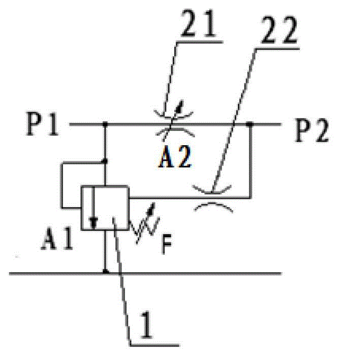
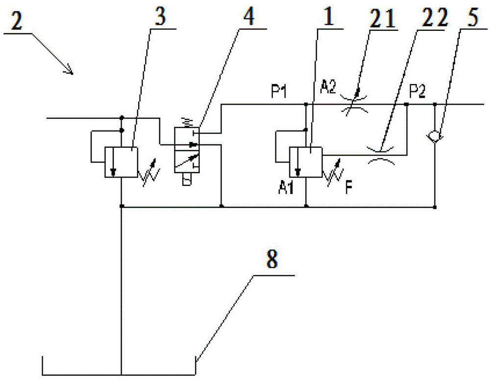
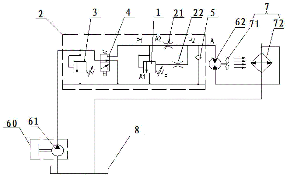
[0048] Below through the accompanying drawings Figure 1 ~ Figure 3 As well as listing some optional embodiments of the present invention, the technical solutions (including preferred technical solutions) of the present invention are further described in detail. It should be noted that: any technical feature and any technical solution in this embodiment are one or more of a variety of optional technical features or optional technical solutions. All the alternative technical features and alternative technical solutions of the present invention are cited, and it is not convenient for the implementation of each technical feature to emphasize that it is one of the optional multiple implementation modes, so those skilled in the art should know: Any technical features and any technical solutions in the embodiments do not limit the protection scope of the present invention, and the protection scope of the present invention should include any alternative technical solutions that those...


PUM


Abstract

An embodiment of the invention discloses a flow control valve, a flow control device and a hydraulic oil heat dissipation system and relates to the technical field of engineering machinery. The flow control valve comprises a three-way pressure compensated valve, a first throttling valve and a second throttling valve; an oil inlet of the first throttling valve is in parallel connection with an oil inlet of the three-way pressure compensated valve; an oil outlet of the first throttling valve is in parallel connection with an oil inlet of the second throttling valve; an oil outlet of the second throttling valve is communicated with a flow feedback oil opening of the three-way pressure compensated valve. The flow control device and the hydraulic oil heat dissipation system comprise the flow control valve. The hydraulic oil heat dissipation system can improve heat dissipation efficiency of a hydraulic oil radiator.

Description

technical field [0001] The invention relates to the technical field of engineering machinery, in particular to a flow control valve, a flow control device provided with the flow control valve, and a hydraulic oil cooling system provided with the flow control device. Background technique [0002] At present, hydraulic oil radiators are used in the hydraulic systems of large machinery such as cranes and dynamic compactors. There are two types of driving methods for hydraulic oil radiators: electric motor drive and hydraulic motor drive. [0003] The characteristic of motor drive is that the driving speed is stable, but it needs the host to provide stable current, which has high requirements on the electrical system of the host. The advantage of the hydraulic motor drive is that the drive torque is large, and the heat dissipation power of the hydraulic oil radiator with the same heat dissipation area driven by the hydraulic motor is 25% to 35% greater than that driven by the m...

Claims


Application Information

Patent Timeline
Patent Type & Authority Patents(China)
IPC IPC(8): F15B13/02F15B21/04
Inventor 罗康松刘可汤洪飞李德芳周波尚君辉
Owner XCMG CONSTR MACHINERY
Learn More