
Portable ramp

a technology of safety equipment and portability, applied in the field of safety, can solve the problems of equipment damage, impediment to movement of moving objects, obstacle damage, etc., and achieve the effect of minimizing the floor space occupied and increasing safety

Pending Publication Date: 2022-10-13
BATCHELDER THOMAS W
View PDF14 Cites 0 Cited by
  • Summary
  • Abstract
  • Description
  • Claims
  • Application Information

AI Technical Summary

Benefits of technology

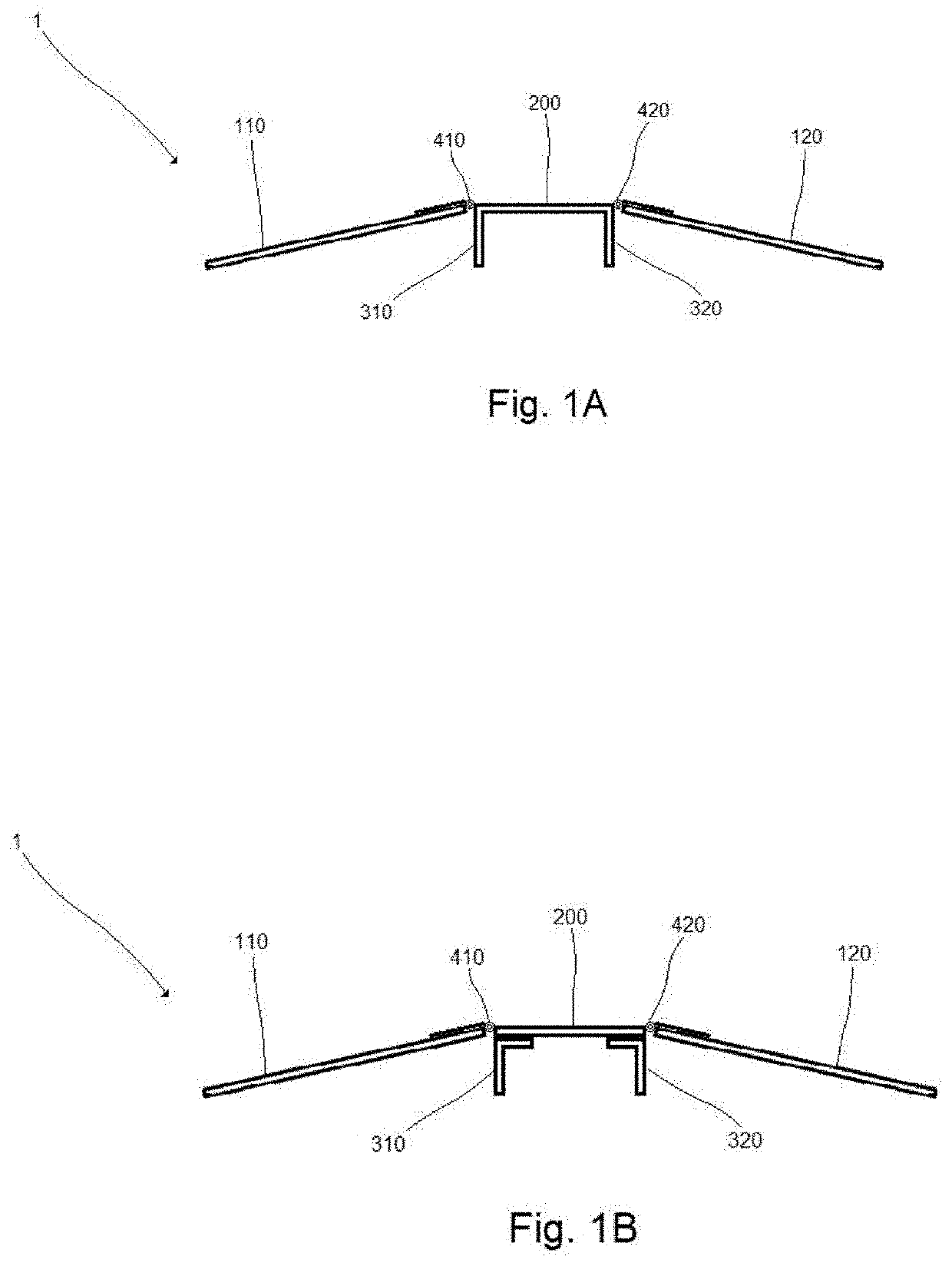
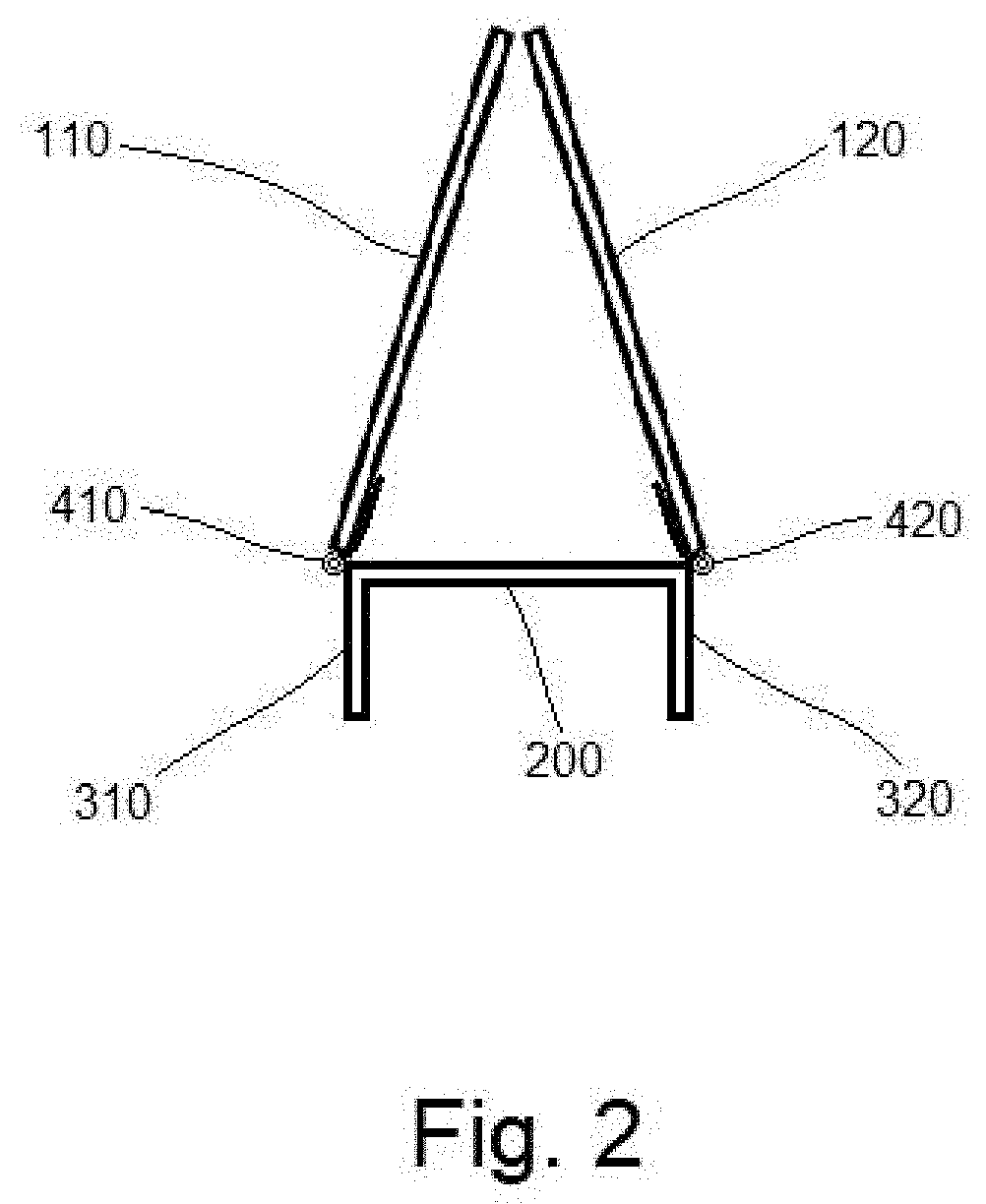
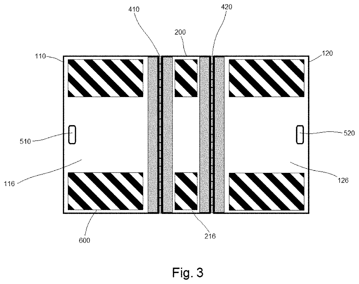
The portable ramp of this patent is a five-components device that can be easily moved and used to help move objects across obstacles. It has a central platform that raises the user a certain height over a support surface, two lateral support members that help keep it stable, and two access ramps that allow objects to be moved from the floor or ground over the obstacle. The access ramps can be folded upwards to save space when not in use. The ramp also has handles for easy carrying and safety graphics to indicate its purpose and sides. This invention provides a convenient and safe solution for moving objects over obstacles.

Problems solved by technology

On a construction job site, inevitably there is a need to move around heavy pieces of equipment, such as scissor lifts, dollies, etc., and inevitably there is some immovable object impeding movement, such as a floor sill, electrical wiring, lumber, etc.
These are not safe methods and can result in damage to the obstacle, damage to the equipment, and potentially injury to the worker.

Method used


Image

  • Portable ramp
  • Portable ramp
  • Portable ramp

Examples


Embodiment Construction

[0016]In one embodiment, the portable ramp 1 of the present invention is comprised of a central platform 200, a first support member 310, a second support member 320, a first access ramp 110, and a second access ramp 120. See FIGS. 1A, 1B, and 4. The first support member 310 is located on the underside 220 of the central platform 200 proximate to the first lateral side 210 of the central platform 200. The second support member 320 is located on the underside 220 of the central platform 200 proximate to the second lateral side 212 of the central platform 200. The first access ramp 110 is hingedly attached to the first lateral side 210 of the central platform 200 by a first hinge 410. The second access ramp 120 is hingedly attached to the second lateral side 212 of the central platform 200 by a second hinge 420.

[0017]In one embodiment, the central platform 200 of the portable ramp 1 is substantially planar and has a substantially rectangular shape. It may have any dimension, though in...


PUM


Abstract

A portable ramp having a central portion and two foldable lateral side portions, whereby the side portions of the ramp are hingedly attached to opposite sides of the central portion of the ramp and a pair of support members are located on the underside of the central portion of the ramp proximate to the hinges, so that the side portions of the ramp can be folded outward and downward to rest on the floor or ground when the portable ramp is deployed for use to travers over an obstacle, and the side portions of the ramp can be folded upwards and inwards when the portable ramp is not in use.

Description

BACKGROUND OF THE INVENTION[0001]The present invention concerns the safety field in general and more specifically portable safety equipment that can be used in the construction industry.[0002]On a construction job site, inevitably there is a need to move around heavy pieces of equipment, such as scissor lifts, dollies, etc., and inevitably there is some immovable object impeding movement, such as a floor sill, electrical wiring, lumber, etc. As a result, ad hoc methods for maneuvering the equipment over the obstacle arise, such as laying a sheet of plywood over the object, or a drywall panel, or even just rolling the equipment directly over the obstacle. These are not safe methods and can result in damage to the obstacle, damage to the equipment, and potentially injury to the worker. This situation also can occur in many other contexts, apart from construction sites, such as at loading docks, at entrances to walk-in coolers and freezers, and the like.[0003]It is therefore shown that...

Claims


Application Information

Patent Timeline
Patent Type & Authority Applications(United States)
IPC IPC(8): E01D15/12B65G69/30
CPCE01D15/124B65G69/30B66F7/243
Inventor BATCHELDER, THOMAS W.
Owner BATCHELDER THOMAS W
Learn More