Transformer

a transformer and transformer technology, applied in the field of transformers, can solve the problems of inconvenient and thinness of transformers, and achieve the effect of reducing the number of transformers

Inactive Publication Date: 2003-06-24
MURATA MFG CO LTD
View PDF11 Cites 39 Cited by
  • Summary
  • Abstract
  • Description
  • Claims
  • Application Information

AI Technical Summary

Benefits of technology

By forming the middle leg with either a circular shape or a substantially elliptical shape, the central portion of the coil can be fitted thereto without any gap, thereby making it possible to further reduce the amount of dead space.
Similarly, by forming the curved portion of the cross-sectional outer peripheral form of the middle leg into the shape of a circular arc formed concentrically with a curved portion of the outer peripheral boundary of the winding accommodating portion, and forming the outer periphery of the winding accommodating portion so that it is close to or coincident with a side portion of the external outline of the magnetic core, the footprint of the transformer can be minimized.
Since a coil lead can be drawn out from an opening at a portion where the outer periphery of the winding accommodating portion is adjacent to a corresponding side of the first magnetic core, it is no longer necessary to provide a separate opening for passing the lead therethrough.
A winding width of the winding accommodating portion may be greater than a thickness of the winding accommodating portion, and the width of the transformer may be greater than its height. This contributes to reducing the thickness of the transformer.
By virtue of this structure, it is possible to restrict the reduction of induction caused by the concentration of magnetic flux at other portions of the magnetic core.

Problems solved by technology

However, in the conventional structure whose size is obtained by adding the size of the outer leg of the corresponding core to the external size of the corresponding coil, the footprint area and overall size of the transformer become considerably greater than those of the corresponding coil, thereby resulting in the inconvenience that the transformer cannot be made sufficiently small and thin.

Method used


Image

  • Transformer
  • Transformer
  • Transformer

Examples


Embodiment Construction

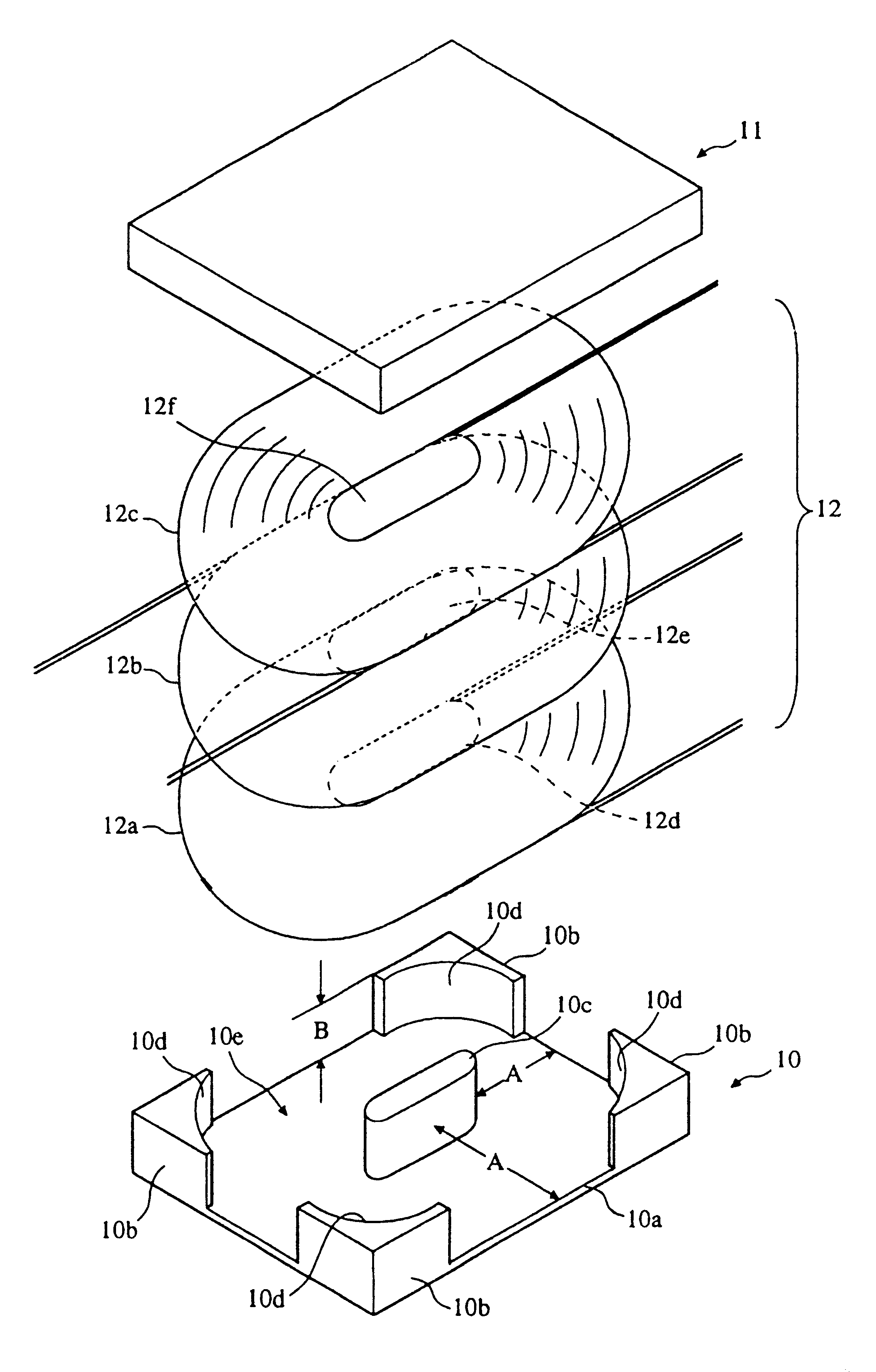
FIG. 1 is an exploded perspective view of an embodiment of a transformer in accordance with the present invention.

The transformer of the embodiment comprises a first magnetic core 10, a second magnetic core 11 which can be placed upon the first magnetic core 10 and secured integrally therewith, for example by use of a suitable adhesive, and a coil 12. The coil 12 comprises three layers that are stacked upon each other in the first magnetic core 10.

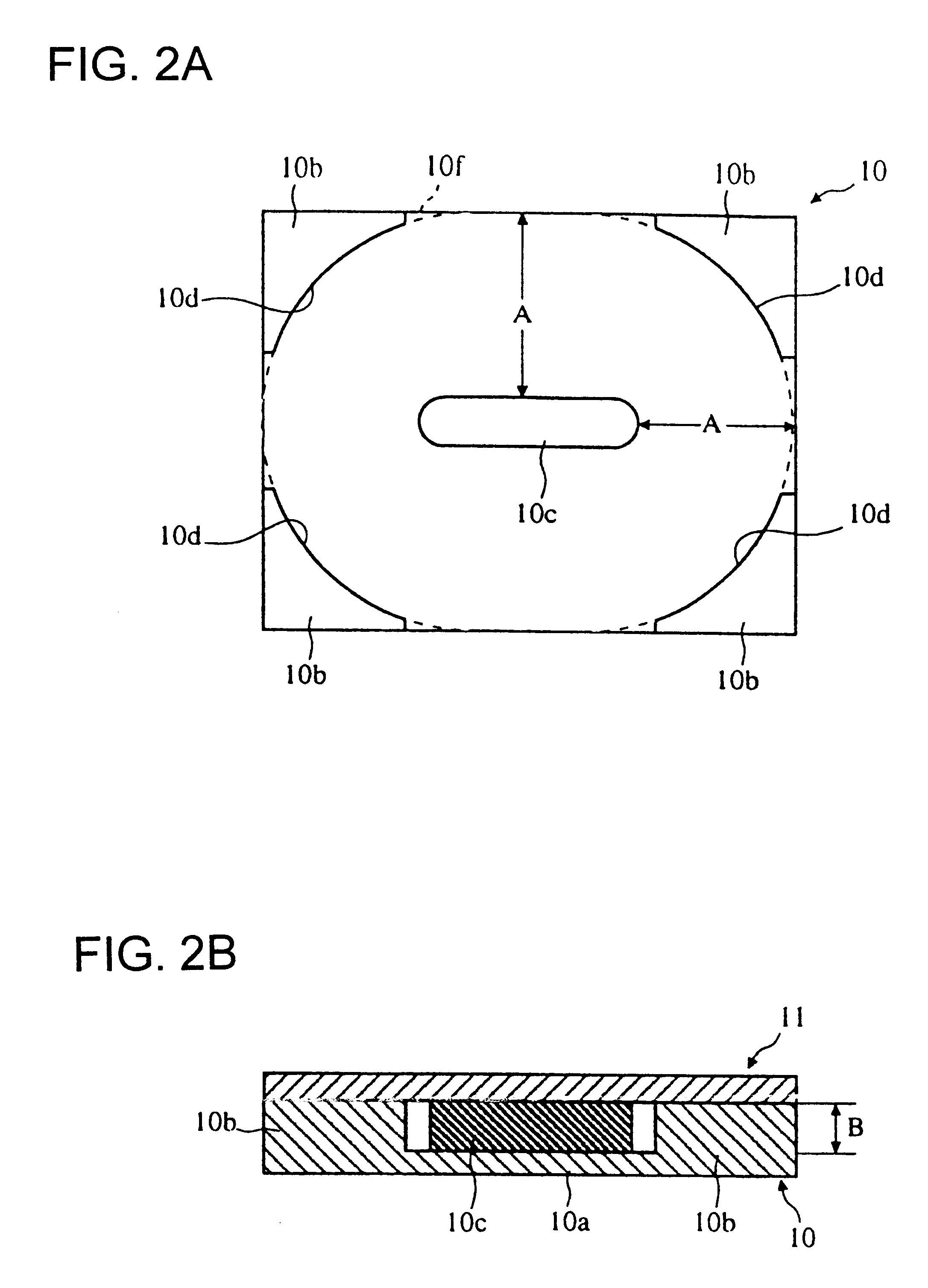
The first magnetic core 10 is formed of, for example, a ferrite material, and comprises a rectangular flat plate 10a, outer legs 10b provided in a standing manner at the four comers of the flat plate 10a, and a middle leg 10c provided in a standing manner at the center of the flat plate 10a. Each outer leg 10b is substantially L-shaped in cross-section, in plan view, with the inner side of each leg 10b being formed as a circular-arc-shaped surface 10d. Although in the embodiment the flat plate 10a used is rectangular, it does not need to b...


PUM

PropertyMeasurementUnit
widthaaaaaaaaaa
thicknessaaaaaaaaaa
width dimensionaaaaaaaaaa

Abstract

A transformer including a first magnetic core and a second magnetic core having the shape of a flat plate. In the first magnetic core, a middle leg and substantially L-shaped outer legs whose inner sides are formed as circular-arc-shaped surfaces are provided in a standing manner at the central portion and at the comers of a rectangular flat plate, respectively. In addition, in the first magnetic core, a winding accommodating portion is formed between the circular-arc-shaped surfaces of the corresponding outer legs and an outer peripheral surface of the middle leg. Three coil portions, formed by spiral winding operations in level states, are placed upon each other, and are inserted into the winding accommodating portion of the first magnetic core. Then, from above the coil portions, the second magnetic core is placed thereon in order to form an integral structure. At this time, at the side portions of the flat plate, an external line of the flat plate and an external line of the winding accommodating portion coincide with each other. Therefore, the footprint of the transformer becomes small. Accordingly, in the invention, the transformer can be made smaller and thinner as a result of making the dead space that exists during the mounting of the coil to the magnetic core as small as possible.

Description

1. Field of the InventionThe present invention relates to a transformer for use in communications devices or various power supplies, and, more particularly, to a transformer which can be reduced in size and which can be made thinner by an improved shape of a magnetic core.2. Description of the Related ArtFIGS. 8A and 8B are sectional front and sectional plan views of a conventional transformer such as those disclosed in, for example, Japanese Unexamined Utility Model Application Publication Nos. 6-70223 and 6-55222. In these figures, a coil 3 is accommodated inside of a cylindrical outer leg 1 and disposed around a middle leg 2. Transformers which are combinations of E-type magnetic cores or which are combinations of E-type magnetic cores and I-type magnetic cores, with a coil being wound upon a middle leg thereof, have also been used. In the structures of such transformers, the sizes of the transformers are obtained by adding the sizes of the outer legs of the corresponding cores t...

Claims


Application Information

Patent Timeline
Patent Type & Authority Patents(United States)
IPC IPC(8): H01F27/255H01F17/04H01F30/00
CPCH01F27/255H01F17/043
Inventor KOYAMA, TAKANORIHOSOTANI, TATSUYATAKEMURA, HIROSHI
Owner MURATA MFG CO LTD
Why Eureka
Try Eureka