Wafer engine

a transfer system and efem technology, applied in the direction of conveyor parts, electrical equipment, thin material processing, etc., can solve the problems of complex overall system tolerances, complex maintenance, and difficulty in adjusting separate controllers, so as to reduce the footprint of efem, accurate and precise positioning of front load components, and easy removal

Inactive Publication Date: 2006-06-08
ALTERA CORP +1
View PDF17 Cites 38 Cited by
  • Summary
  • Abstract
  • Description
  • Claims
  • Application Information

AI Technical Summary

Benefits of technology

[0026] Yet another aspect of the present invention is to accurately and precisely locate the front load components with respect to each other. Preferably, this calibration process is accomplished with a minimum number of adjustments. In one embodiment, all the interior and exterior EFEM components are precisely tied to the unified frame such that they share common reference points.
[0027] Yet another aspect of the present invention is to provide a unified frame that segregates and isolates the port door/carrier door assembly from the many of the interior EFEM components. In one embodiment, the port door/carrier door assembly is lowered into a separate air flow/storage area located within the mini-environment. The storage area prevents particles created by, for example, a wafer handling robot, from contaminating the assembly.
[0028] Still another aspect of the present invention is to provide a wafer carrier docking/interface plate that can be easily removed from the EFEM to access the interior of the EFEM. In one embodiment of the present invention, the removable plate is manufactured from a transparent material so that a user may observe a

Problems solved by technology

It is a disadvantage to prior art EFEMs that the overall system tolerances are compounded with each frame member, panel and component connection.
The result is that the assembled EFEM components are poorly aligned and need to be adjusted to the proper position with respect to each other.
The separate controllers also complicate maintenance and add to the parts and electrical connections provided in the EFEM.
Further

Method used


Image

  • Wafer engine
  • Wafer engine
  • Wafer engine

Examples


Embodiment Construction

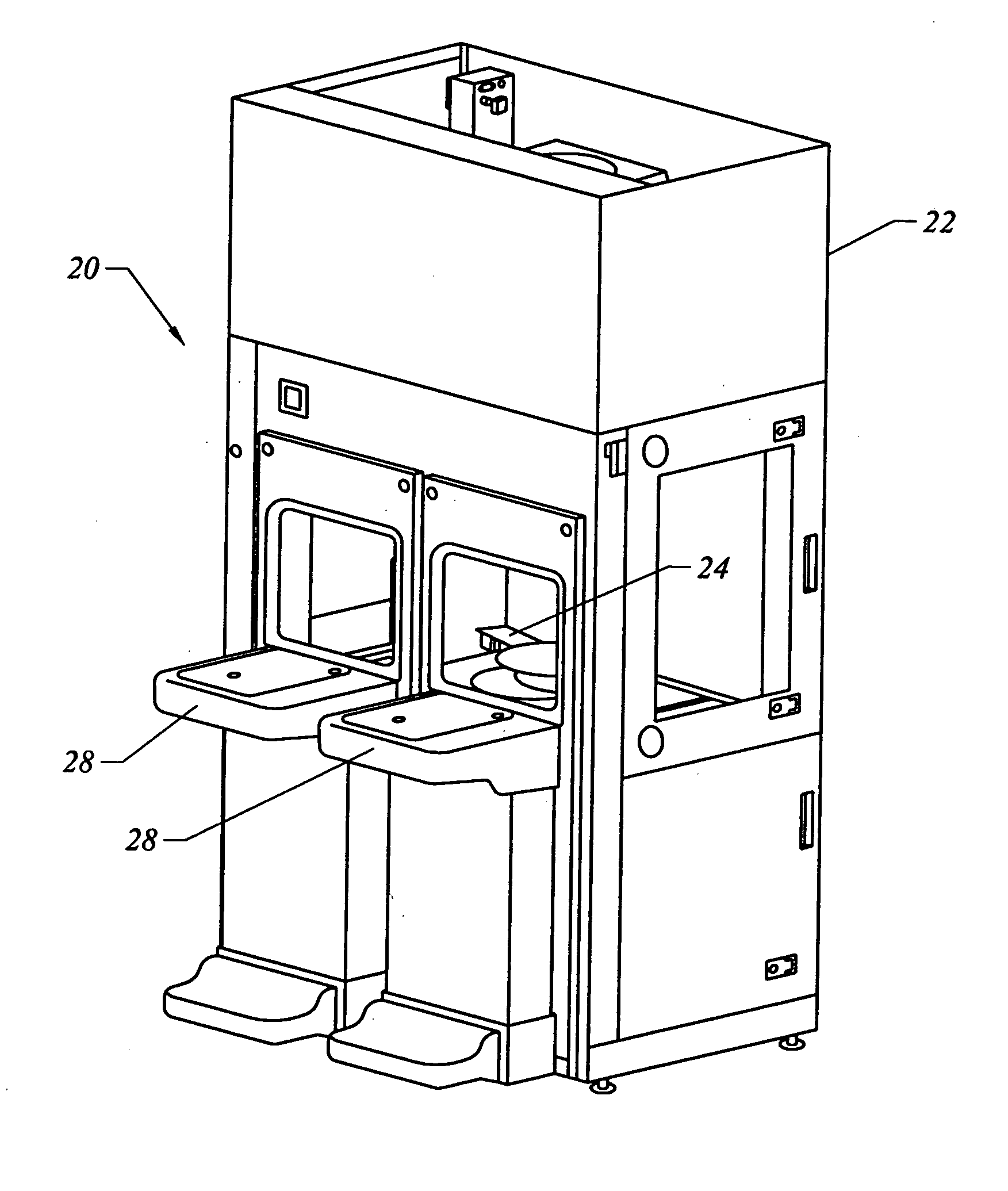
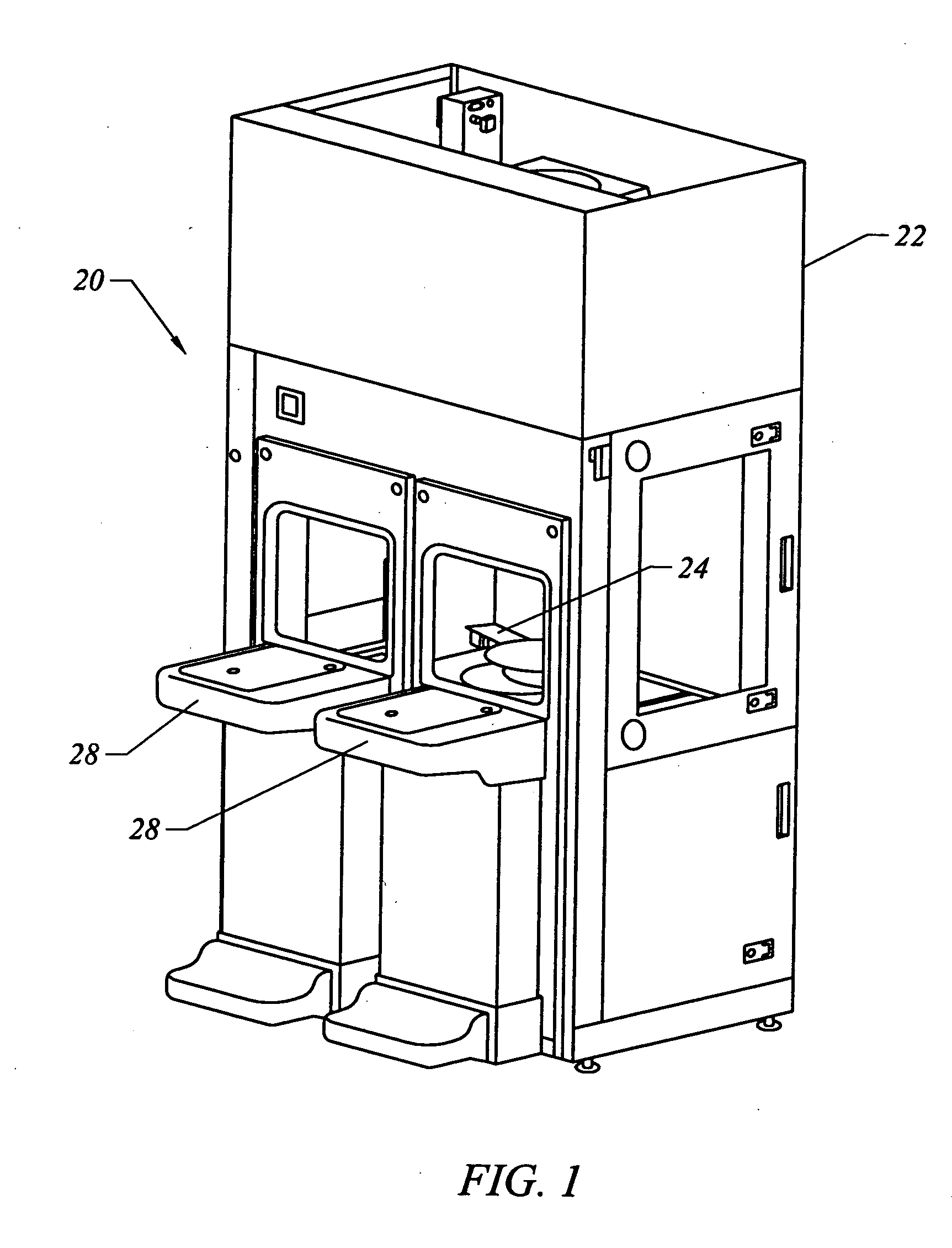
[0036]FIG. 1 is a perspective view of a conventional front end assembly in accordance with the prior art;

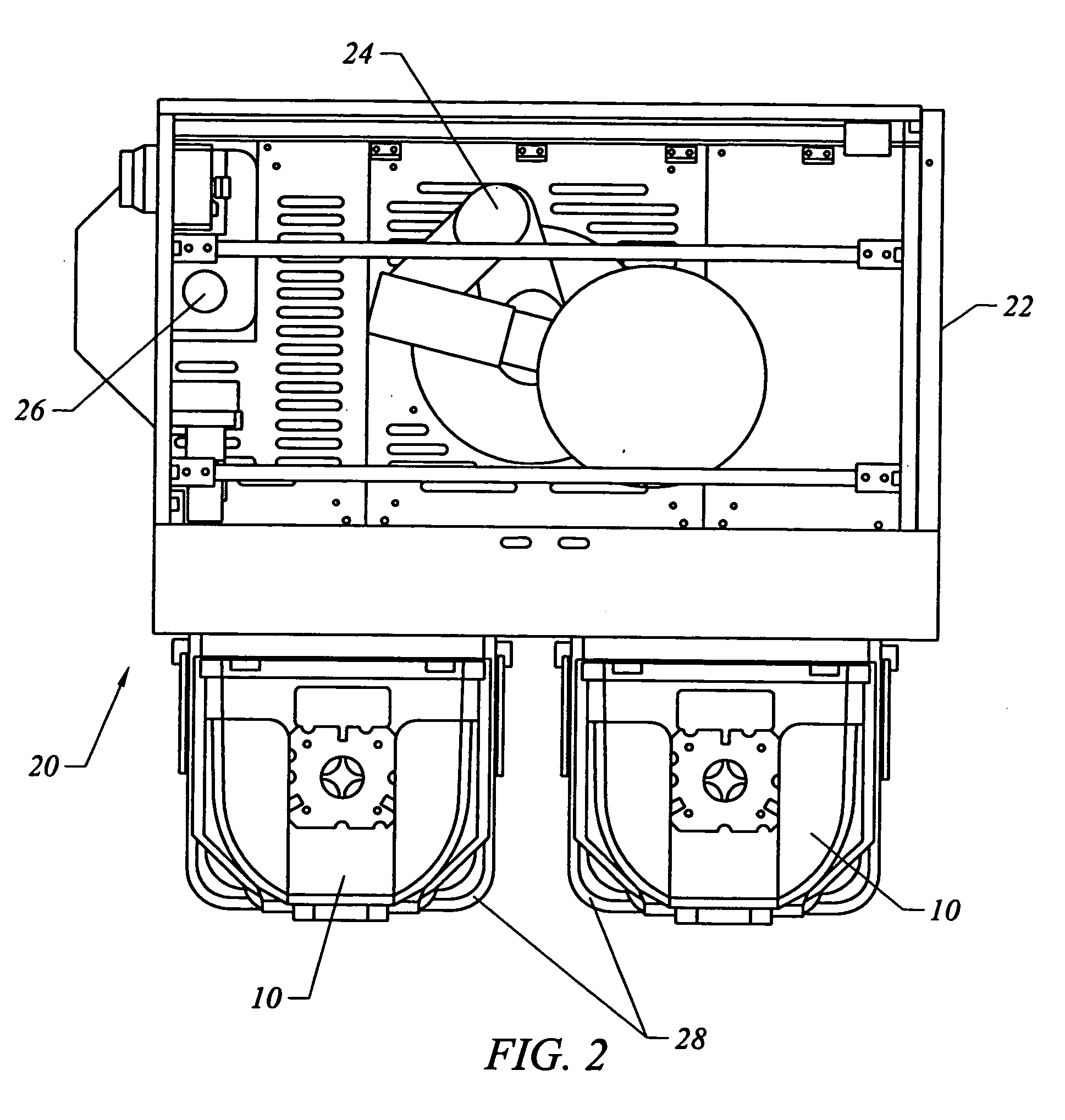
[0037]FIG. 2 is a top view of the front end assembly shown in FIG. 1;

[0038]FIG. 3 is a side view of a conventional front end assembly in accordance with the prior art;

[0039]FIG. 4 is a perspective view of an embodiment of the spine structure, according to the present invention;

[0040]FIG. 5 is a partial exploded view of the spine structure shown in FIG. 4;

[0041]FIG. 6 is a perspective view of an embodiment of a FOUP docking interface, according to the present invention;

[0042]FIG. 7 is a partial exploded perspective view of an embodiment of the spine structure and front end load components, according to the present invention;

[0043]FIG. 8 is a perspective view of an embodiment of a wafer engine mounted to the spine structure, according to the present invention;

[0044]FIG. 9 is a perspective view of an embodiment of a wafer engine drive rail mounted to the spine structure, acc...


PUM


Abstract

The present invention is a wafer engine for transporting wafers. The wafer engine includes a linear drive for moving the wafer along an x axis, a rotational drive for rotating the wafer about a theta axis, a linear drive for moving the wafer along a z axis, and a linear drive for moving the wafer along a radial axis. The linear drive for moving the wafer along a z axis is offset from the rotational drive. When the rotational drive rotates about the theta axis, both the z axis and radial axis drives are also rotated about the theta axis. Preferably, the linear drive for moving the wafer along a radial axis is a dual or rapid swap slide body mechanism having an upper and lower end effector. The slide body mechanism preferably also has means to align the wafer and perform various inspection and marking procedures.

Description

CLAIM OF PRIORITY [0001] This application claims priority from U.S. patent application Ser. No. 10 / 087,400, entitled “Wafer Engine,” filed Mar. 1, 2002, which claims priority from provisional Application No. 60 / 316,722, entitled “UNIVERSAL MODULAR PROCESSING INTERFACE SYSTEM,” filed Aug. 31, 2001, which is incorporated herein by reference, and is now abandoned. CROSS-REFERENCE TO RELATED APPLICATIONS [0002] 1. U.S. patent application Ser. No. 10 / 087,638, filed Mar. 1, 2002, entitled “UNIFIED FRAME FOR SEMICONDUCTOR MATERIAL HANDLING SYSTEM”; [0003] 2. U.S. patent application Ser. No. 10 / 087,092, filed Mar. 1, 2002, entitled “SEMICONDUCTOR MATERIAL HANDLING SYSTEM”; AND [0004] 3. U.S. patent application Ser. No. 10 / 234,640, filed Sep. 3, 2002, entitled “UNIVERSAL MODULAR WAFER TRANSPORT SYSTEM”.FIELD OF THE INVENTION [0005] The present invention generally relates to a wafer transfer system. More particularly, the present invention is a unified, scalable frame or structure that equipm...

Claims


Application Information

Patent Timeline
IPC IPC(8): H01L21/677H01L21/68H01L21/687
CPCH01L21/67766H01L21/67775H01L21/67778H01L21/68707Y10S414/137H01L21/00
Inventor BONORA, ANTHONY C.GOULD, RICHARD H.HINE, ROGER G.KROLAK, MICHAELSPEASL, JERRY A.
Owner ALTERA CORP
Why Eureka
Try Eureka