Supercharge Your Innovation With Domain-Expert AI Agents!

Imaging lens assembly

a technology of imaging lens and assembly, which is applied in the direction of mountings, instruments, optics, etc., can solve the problems of difficult design and manufacture of imaging lens assemblies

Active Publication Date: 2022-10-13
SNAP INC
View PDF2 Cites 0 Cited by
  • Summary
  • Abstract
  • Description
  • Claims
  • Application Information

AI Technical Summary

Benefits of technology

The patent text describes an imaging lens assembly that can maintain focus over a wide range of temperatures. The technical effect of this invention is to provide an imaging lens assembly that can maintain focus even when exposed to extreme temperatures, which can occur in various situations such as extreme weather or in the process of manufacturing. The lens assembly includes five plastic elements and an optional sixth plastic element, which can be a null-power or low-power element. The design of the lens assembly can be adjusted to achieve desired optical properties and can be used in various imaging devices.

Problems solved by technology

It is difficult to design and manufacture an imaging lens assembly that maintains its focus over a suitable wide range of temperatures.

Method used


Image

  • Imaging lens assembly
  • Imaging lens assembly
  • Imaging lens assembly

Examples


example 1

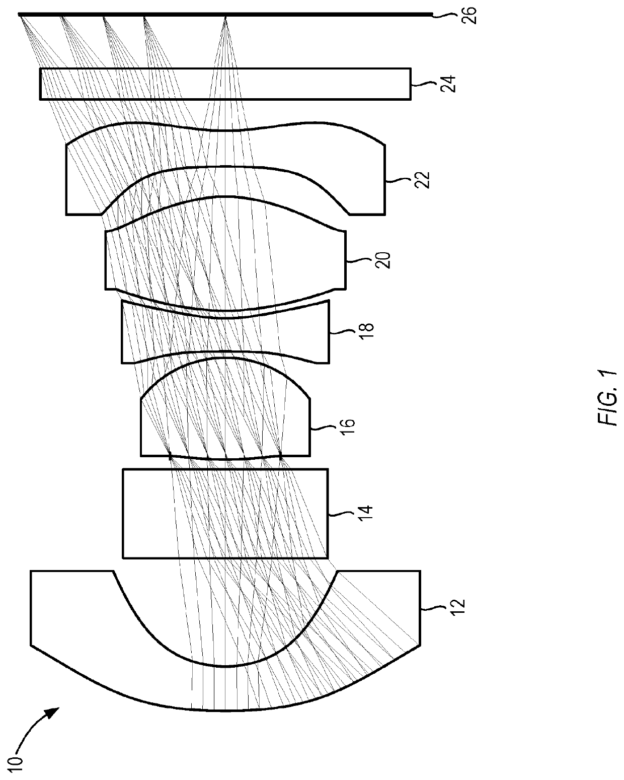
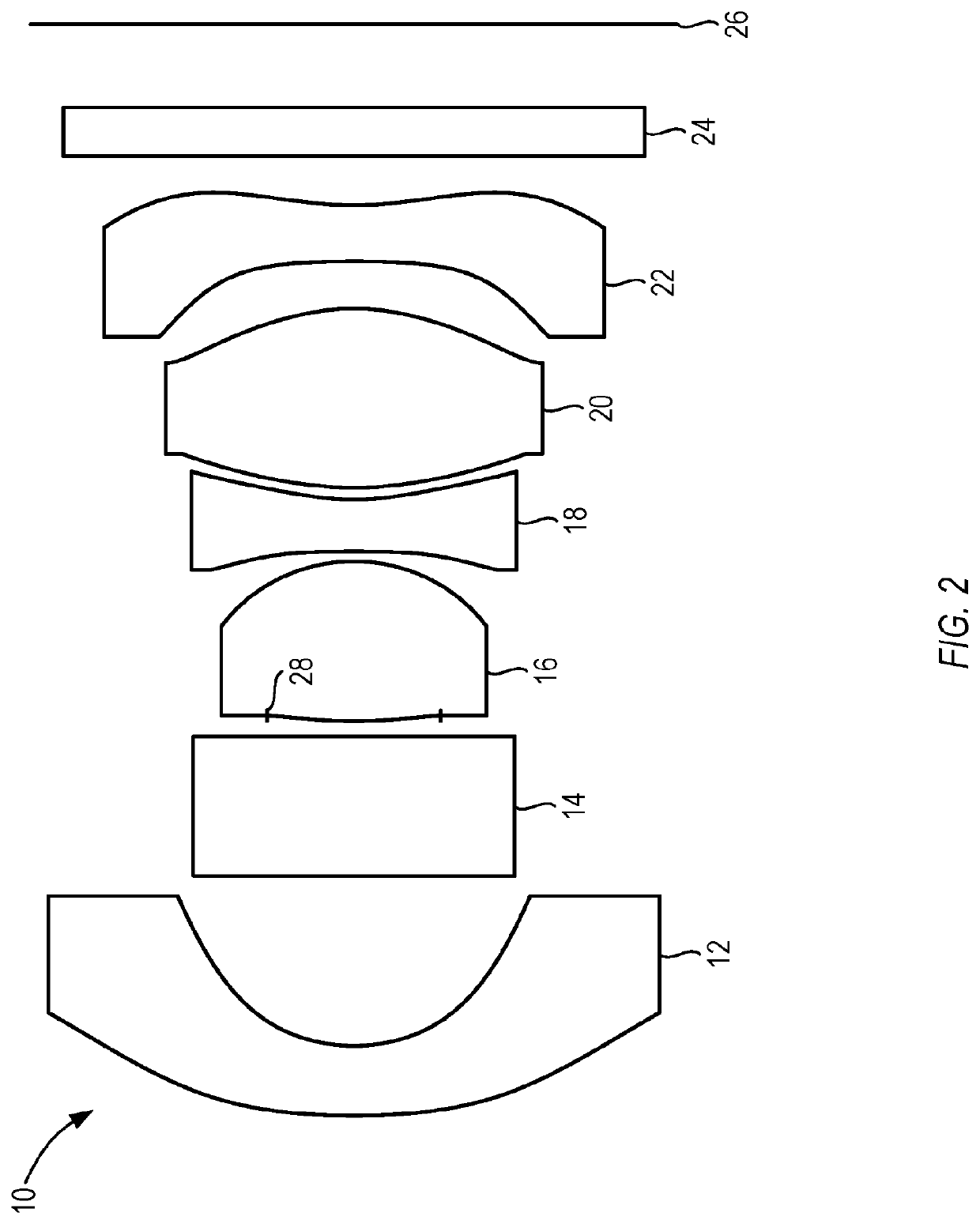
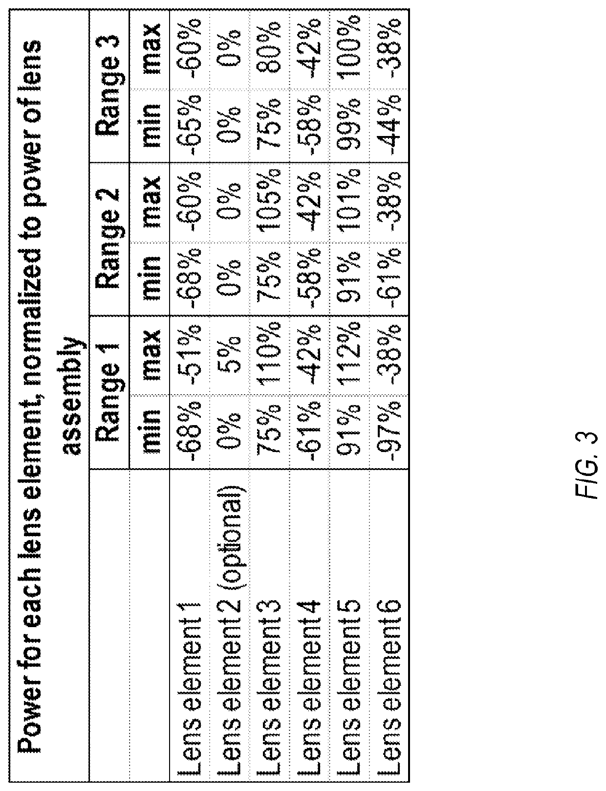
[0058] An imaging lens assembly having a positive total refractive power, the imaging lens assembly comprising in order from an object side to an image side: a first lens element with negative refractive power between 51% and 68% of the total refractive power; a second lens element with zero or positive refractive power between 0% and 5% of the total refractive power; a third lens element with positive refractive power between 75% and 110% of the total refractive power; a fourth lens element with negative refractive power between 42% and 61% of the total refractive power; a fifth lens element with positive refractive power between 91% and 112% of the total refractive power; and a sixth lens element with a negative refractive power between 38% and 97% of the total refractive power.

example 2

[0059] The imaging lens assembly of example 1, wherein the first, second, third, fourth, fifth, and sixth elements are formed from plastic.

example 3

[0060] The imaging lens assembly of any one of examples 1-2, wherein the first, second, third, fourth, fifth, and sixth elements are mounted in a plastic barrel and are spaced apart by plastic spacers.

[0061]Example 4: The imaging lens assembly of any one of examples 1-3, wherein: the first lens element is formed from a material having an Abbe number greater than 50; the second lens element is formed from a material having an Abbe number less than 35; the third lens element is formed from a material having an Abbe number greater than 50; the fourth lens element is formed from a material having an Abbe number less than 27; the fifth lens element is formed from a material having an Abbe number greater than 50; and the sixth lens element is formed from a material having an Abbe number less than 27.

[0062]Example 5: The imaging lens assembly of any one of examples 1-4, wherein: the first lens element is formed from a material having a dn / dT less than −99×10−6 / ° C.; the third lens element ...


PUM


Abstract

A multi-element imaging lens can be formed from five plastic elements, and an optional null-power or relatively low power sixth plastic element. The lens can use selected plastic materials to reduce a thermal focal shift. In the lens, negative refractive power elements can be formed from plastic materials having a relatively large negative refractive index variation with temperature, abbreviated as dn / dT, while positive refractive power elements can be formed from plastic materials having a relatively small negative dn / dT. Reducing the thermal focal shift, as disclosed, can eliminate the need for an auto-focusing device, such as a voice coil. Reducing the thermal focal shift, as disclosed, can also eliminate the need to use one or more glass elements to further reduce thermal focal shift, which can reduce cost for the lens.

Description

PRIORITY[0001]This application is a continuation of U.S. application Ser. No. 16 / 483,973, filed Aug. 6, 2019, which application claims the benefit of priority to U.S. Provisional Patent Application Ser. No. 62 / 455,983, filed Feb. 7, 2017, the benefit of priority of which are claimed hereby, and which are incorporated by reference herein in their entirety.FIELD OF THE DISCLOSURE[0002]The present disclosure relates to an imaging lens assembly.BACKGROUND OF THE DISCLOSURE[0003]It is difficult to design and manufacture an imaging lens assembly that maintains its focus over a suitable wide range of temperatures. For example, at particular temperatures, thermal variation of the refractive index of the lens elements can translate the focal plane of the imaging lens assembly toward or away from a sensor, leading to a blurry image on the sensor.SUMMARY[0004]In one example of an imaging lens assembly having a positive total refractive power, the imaging lens assembly can include, in order fro...

Claims


Application Information

Patent Timeline
Patent Type & Authority Applications(United States)
IPC IPC(8): G02B7/02G02B1/04G02B5/22G02B9/62G02B13/00
CPCG02B7/028G02B1/041G02B5/226G02B7/021G02B9/62G02B13/0045G02B13/0055G02B9/60G03B30/00
Inventor BATES, ROBERT MATTHEW
Owner SNAP INC
Features
  • R&D
  • Intellectual Property
  • Life Sciences
  • Materials
  • Tech Scout
  • Unparalleled Data Quality
  • Higher Quality Content
  • 60% Fewer Hallucinations
Learn More