Photonic Crystal Devices Using Negative Refraction

a technology of negative refraction and crystal devices, which is applied in the direction of lenses, instruments, optical elements, etc., can solve the problems of restricting the application of this type of material and high loss expected

Inactive Publication Date: 2009-04-02
NORTHEASTERN UNIV
View PDF4 Cites 21 Cited by
  • Summary
  • Abstract
  • Description
  • Claims
  • Application Information

AI Technical Summary

Benefits of technology

[0008]In a further embodiment, a plano-concave lens composed of homogeneous material of sufficiently large refractive index with aspherical corrugated surface acting as a diffraction grating displays minimum aberration and optimum focusing.

Problems solved by technology

Since the material has negative refraction only in the neighborhood of resonances, high loss is expected.
This severely restricts the application of this type of material.

Method used


Image

  • Photonic Crystal Devices Using Negative Refraction
  • Photonic Crystal Devices Using Negative Refraction
  • Photonic Crystal Devices Using Negative Refraction

Examples


Embodiment Construction

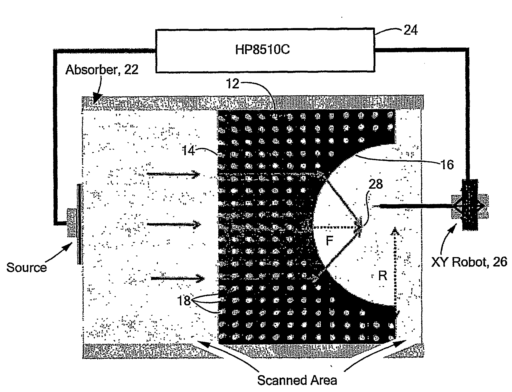
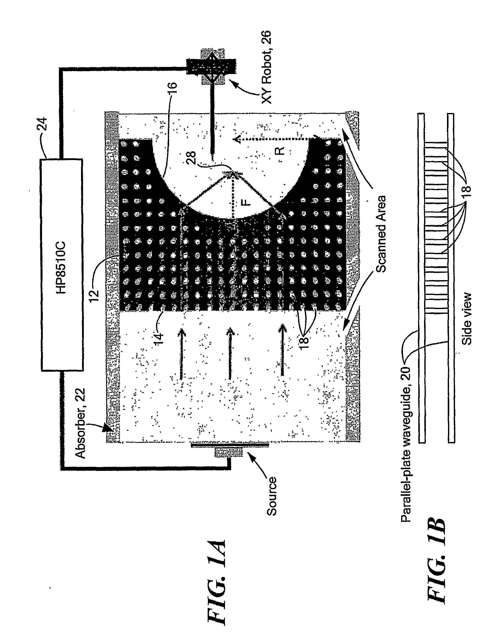
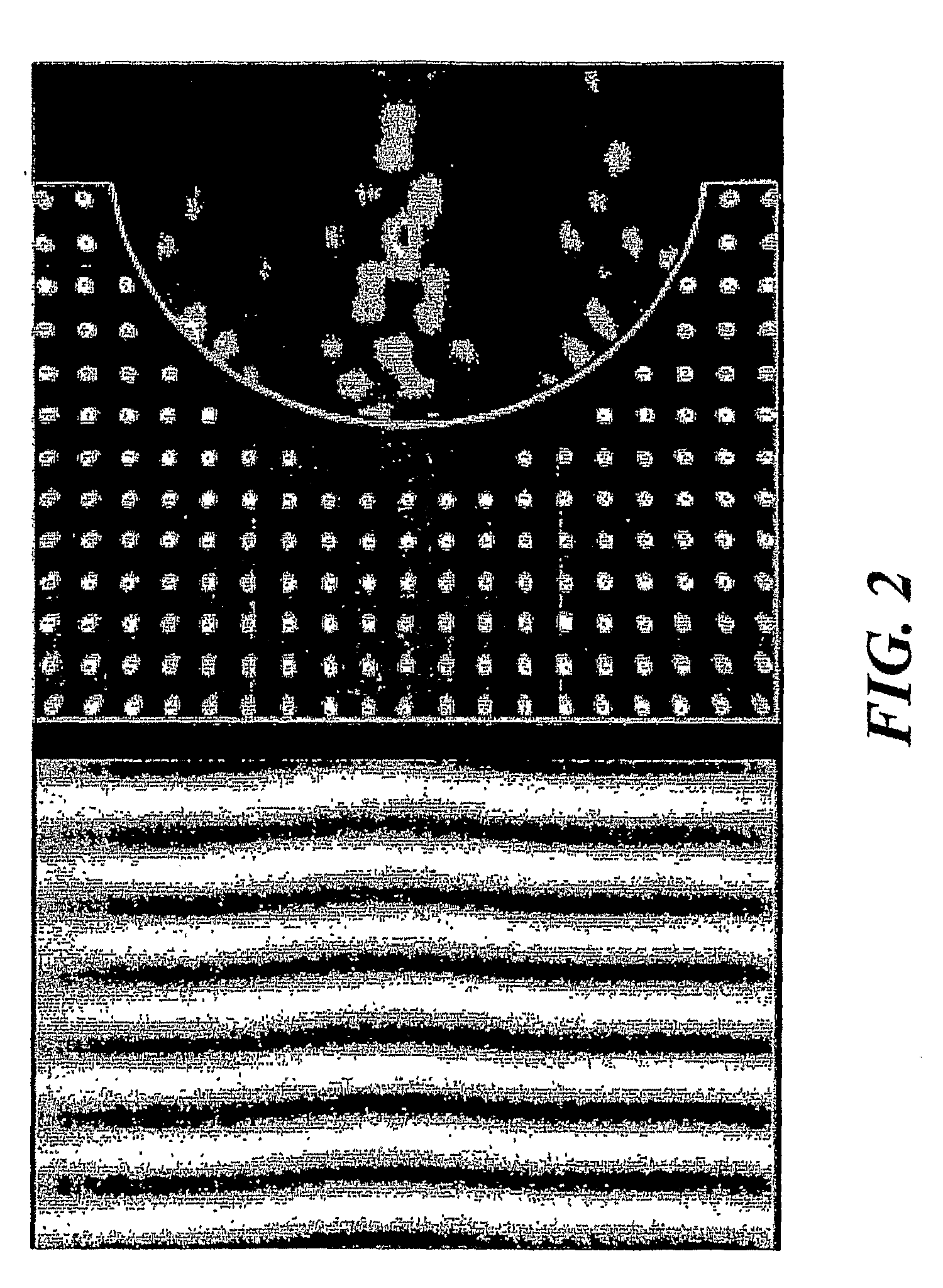
[0026]The present invention relates to a dielectric photonic crystal having a negative refractive index used for focusing of electromagnetic radiation. Referring to FIGS. 1A and 1B, a plano-concave lens 10 is formed from a dielectric photonic crystal 12. The lens includes one planar face 14 and one concavely curved circular face 16. The lens is comprised of a two-dimensional periodic array of rods 18 of a suitable material, such as alumina or silicon, arranged in a square lattice in a medium such as air. A waveguide 20 directs electromagnetic radiation toward the planar face. The lens can be used with any frequency of electromagnetic radiation; it is particularly useful with microwave or optical frequencies. Alumina is a suitable material for microwave frequencies; silicon is a suitable material for optical frequencies. Other materials with high dielectric constant and low loss can also be used to fabricate the photonic crystals. An absorber 22 is used to form a microwave beam. A ne...


PUM


Abstract

Negative refraction in photonic crystals and diffraction grating is used to design plano-concave lenses to focus plane waves. Microwave experiments are carried out to demonstrate negative refraction and the performance of these lenses. Demonstration of negative refraction of visible light is also performed for the grism. These lenses can be used in optical circuits, astronomical applications, etc.

Description

CROSS REFERENCE TO RELATED APPLICATIONS[0001]This application claims the benefit under 35 U.S.C. § 119(e) of U.S. Provisional Patent Application No. 60 / 681,521, filed on May 16, 2005, the disclosure of which is incorporated by reference herein.STATEMENT REGARDING FEDERALLY SPONSORED RESEARCH OR DEVELOPMENT[0002]This invention was made under Air Force Research Laboratories, Hanscom AFB, Contract No. F33615-01-1-1007 and NSF Grant No. PHY-0457002. The government has certain rights in this invention.BACKGROUND OF THE INVENTION[0003]Two types of materials can exhibit negative refraction and thus possess negative refractive indices. One is the wire and split-ring resonator metamaterial. The other is the photonic crystal.[0004]A metamaterial has a crystal structure which has a lattice spacing much less than the operating wave length. The mechanism is to invoke electric and magnetic resonances so that this artificial structure can have negative permittivity and permeability simultaneously....

Claims


Application Information

Patent Timeline
Patent Type & Authority Applications(United States)
IPC IPC(8): G02B3/00G02B1/02G02B27/44
CPCB82Y20/00G02B6/1225G02B1/007
Inventor LU, WENTAO T.SRIDHAR, SRINIVASVODO, PLARENTAPARIMI, PATANJALIHUANG, YONGJIAN
Owner NORTHEASTERN UNIV
Why Eureka
Try Eureka