Optical path splitting element and image display apparatus using the same

a technology of optical path splitting and image display apparatus, which is applied in the direction of optical elements, television systems, instruments, etc., can solve the problems of unfavorable wide field angle viewing optical system,

Inactive Publication Date: 2003-04-17
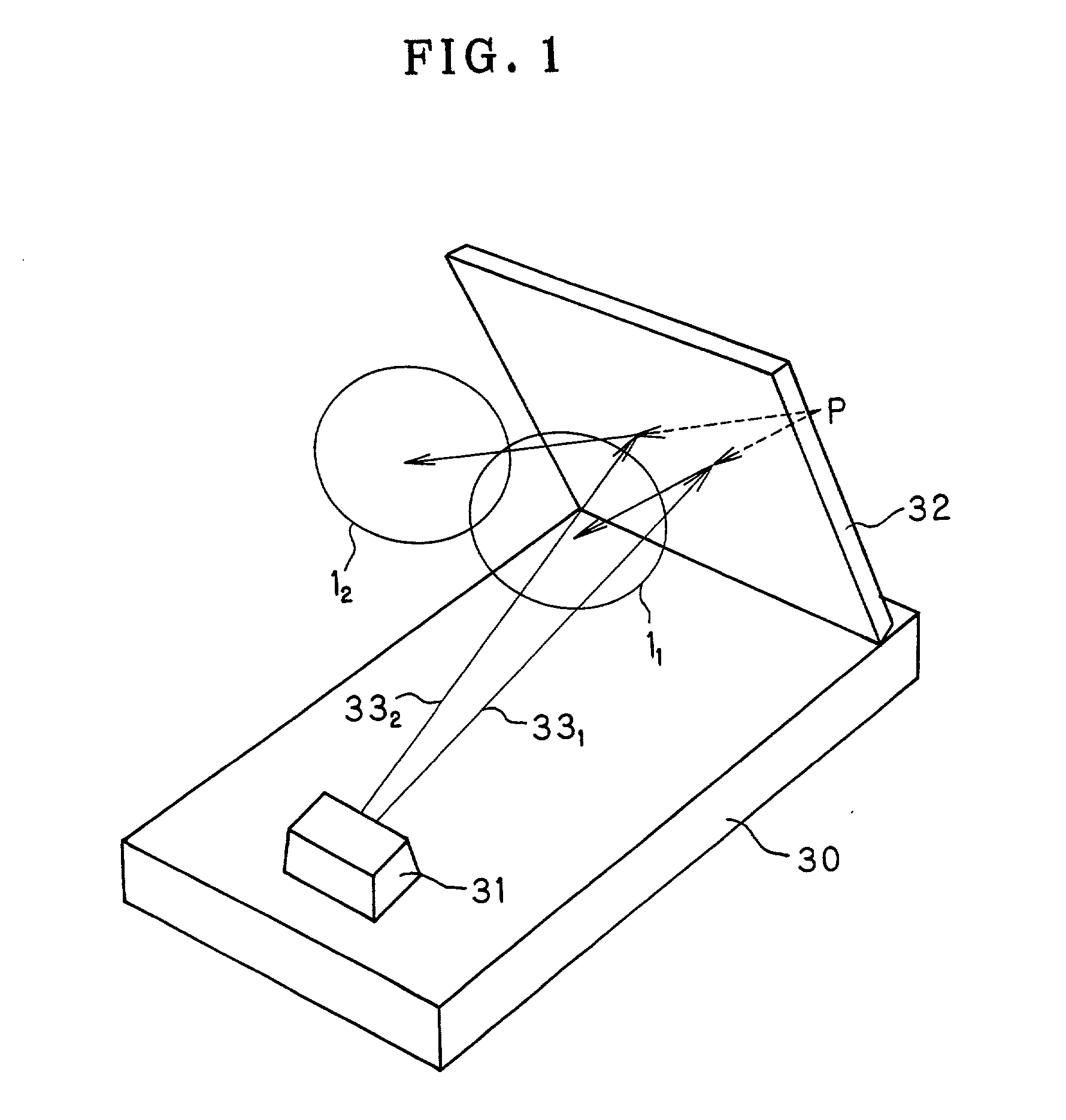
OLYMPUS CORP
View PDF0 Cites 5 Cited by
  • Summary
  • Abstract
  • Description
  • Claims
  • Application Information

AI Technical Summary

Benefits of technology

[0016] It is known that an optical system that is compact and has minimal aberrations can be constructed by using a decentered prism as an optical element.
[0019] Meanwhile, a reflecting optical element such as a mirror or a prism produces no chromatic aberration in theory even when a reflecting surface thereof is provided with a power, and need not add another optical element only for the purpose of correcting chromatic aberration. Accordingly, an optical system using a reflecting optical element allows the number of constituent optical elements to be reduced from the viewpoint of chromatic aberration correction in comparison to an optical system using a refracting optical element.
[0020] At the same time, a reflecting optical system using a reflecting optical element allows the optical system itself to be compact in size in comparison to a refracting optical system because the optical path is folded in the reflecting optical system.
[0022] Furthermore, a prism has an entrance surface and an exit surface, which are refracting surfaces, and a reflecting surface. Therefore, the degree of freedom for aberration correction is high in comparison to a mirror, which has only a reflecting surface. In particular, if the prism reflecting surface is assigned the greater part of the desired power to thereby reduce the powers of the entrance and exit surfaces, which are refracting surfaces, it is possible to reduce chromatic aberration to a very small quantity in comparison to refracting optical elements such as lenses while maintaining the degree of freedom for aberration correction at a high level in comparison to mirrors. Furthermore, the inside of a prism is filled with a transparent medium having a refractive index higher than that of air. Therefore, it is possible to obtain a longer optical path length than in the case of air. Accordingly, the use of a prism makes it possible to obtain an optical system that is thinner and more compact than those formed from lenses, mirrors and so forth, which are placed in the air.
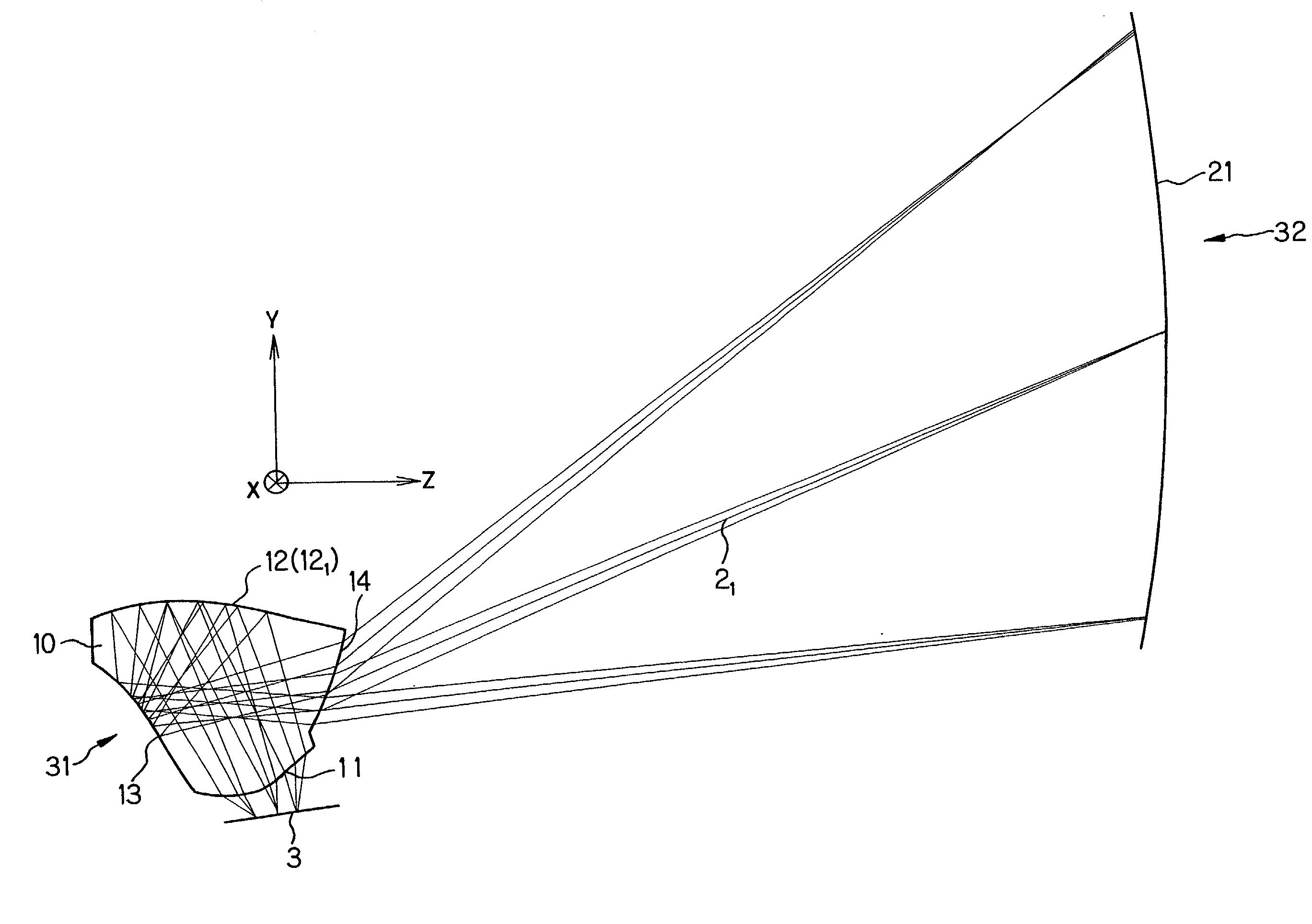
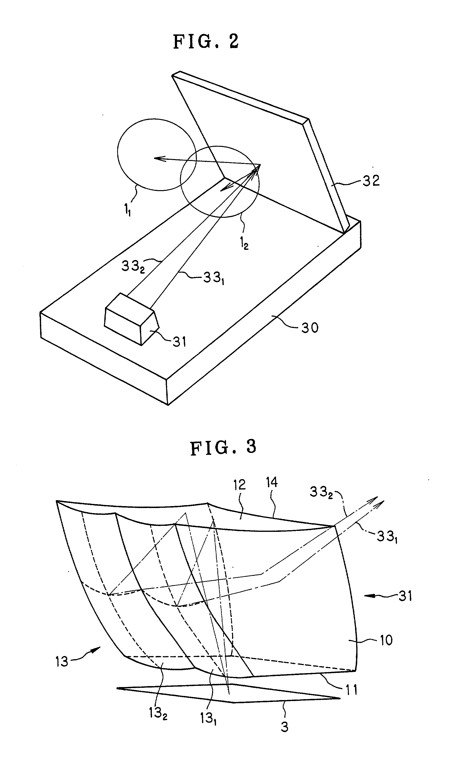
[0025] Thus, the present invention has succeeded in imparting an optical path splitting function to such a decentered prism by constructing at least one surface of the decentered prism in the form of a discontinuous surface comprising at least two surfaces adjacent to each other. The discontinuous surface can split a light beam from an object (image display device) into at least two light beams and allows aberration correction to be performed individually by the at least two optical functional surfaces and, at the same time, permits the optical axes to be separated by a desired distance and at a desired angle.

Problems solved by technology

Therefore, it is difficult to construct a viewing optical system of wide field angle.
In the above-described conventional optical path splitting element that splits the light beam into two optical paths extending in different directions, the size of the optical path splitting element becomes unfavorably large.
Accordingly, an image display apparatus using the optical path splitting element becomes undesirably large in size and heavy in weight.
The above-described conventional method of splitting an optical path by using a half-mirror suffers from the problem that the image for observation becomes unfavorably dark because the light quantity is halved for each optical path.
Accordingly, when rays are refracted at the interface surface of the lens, chromatic aberration unavoidably occurs according to chromatic dispersion characteristics of the refracting optical element.
However, among reflecting optical elements, prisms, in which the positional relationship between surfaces is fixed, only need to control decentration as a single unit of prism and do not need high assembly accuracy and a large number of man-hours for adjustment as are needed for other reflecting optical elements.
If only one decentered prism or only one concave mirror is used, it is impossible to correct decentration aberrations completely.
If the image display apparatus is arranged to increase the exit pupil diameter thereof without using the optical path splitting element, the load imposed on the relay optical system for aberration correction becomes excessively heavy.
Consequently, it becomes impossible for a compact relay optical system to provide an observation image favorably corrected for aberrations.
Consequently, decentration aberrations occur to a considerable extent unfavorably.
In particular, the occurrence of decentration aberrations in the projection of the pupil causes pupil aberrations.
This causes an image distortion and narrows the observation area, undesirably.

Method used


Image

  • Optical path splitting element and image display apparatus using the same
  • Optical path splitting element and image display apparatus using the same
  • Optical path splitting element and image display apparatus using the same

Examples


example 1

7 Example 1 Surface Radius of Surface Displacement Refractive Abbe's No. curvature separation and tilt index No. Object .infin. -1000.00 plane 1 .infin. (Pupil ) 2 FFS{circle over (1)} (RE) (1) 3 FFS{circle over (2)} (2) 1.5254 56.2 4 FFS{circle over (3)} (RE) (3) 1.5254 56.2 5 FFS{circle over (4)} (RE) (4) 1.5254 56.2 6 FFS{circle over (5)} (5) Image .infin. (6) plane FFS1 C.sub.4 -4.3277 .times. 10.sup.-3 C.sub.6 -3.1324 .times. 10.sup.-3 C.sub.8 6.5334 .times. 10.sup.-6 C.sub.10 5.7777 .times. 10.sup.-6 FFS2 C.sub.4 3.5167 .times. 10.sup.-2 C.sub.6 -5.9257 .times. 10.sup.-2 C.sub.8 -4.5764 .times. 10.sup.-3 C.sub.10 -1.2743 .times. 10.sup.-4 FFS3 C.sub.4 -1.8901 .times. 10.sup.-3 C.sub.5 1.7416 .times. 10.sup.-2 C.sub.6 -5.5547 .times. 10.sup.-2 C.sub.7 3.1408 .times. 10.sup.-4 C.sub.8 -2.7604 .times. 10.sup.-3 C.sub.9 -2.6486 .times. 10.sup.-3 C.sub.10 1.3332 .times. 10.sup.-3 FFS4 C.sub.4 -1.9553 .times. 10.sup.-2 C.sub.6 -3.0093 .times. 10.sup.-2 C.sub.8 -2.4995 .times. 10.sup...


PUM


Abstract

An optical path splitting element for splitting a light beam from a single object into at least two optical paths is made compact in size by using a three-dimensional optical system and given a power to reduce the number of components thereof. An image display apparatus uses the optical path splitting element. The optical path splitting element has a prism member having an entrance surface through which the light beam from the object enters the prism member, at least one reflecting surface reflecting the light beam within the prism member, and an exit surface through which the light beam exits the prism member. The prism member has at least one rotationally asymmetric surface. At least one optical functional surface is a discontinuous surface formed from at least two surfaces adjacent to each other. The other optical functional surfaces are common to the at least two optical paths.

Description

[0001] This application claims benefit of Japanese Application No. 2001-127806 filed in Japan on Apr. 25, 2001, the contents of which are incorporated by this reference.[0002] 1. Field of the Invention[0003] The present invention relates to an optical path splitting element and an image display apparatus using the same. More particularly, the present invention relates to an optical path-splitting element for splitting a light beam from a single object into two optical paths and also relates to a head- or face-mounted image display apparatus using such an optical path splitting element.[0004] 2. Discussion of Related Art[0005] There has heretofore been known an optical path splitting element for leading an image displayed on a single display device to both eyes of an observer, as disclosed in Japanese Patent Application Unexamined Publication Number (hereinafter referred to as "JP(A)") Hei 9-181999. This splitting element uses a single prism to split a light beam from the displayed i...

Claims


Application Information

Patent Timeline
Patent Type & Authority Applications(United States)
IPC IPC(8): G02B17/08G02B25/00G02B27/00G02B27/01G02B27/02H04N5/64
CPCG02B2027/0156G02B27/0172
Inventor TOGINO, TAKAYOSHI
Owner OLYMPUS CORP
Why Eureka
Try Eureka