Optical recording medium tilt compensation device, tilt compensation method, and optical information recording apparatus

a technology of optical information and recording medium, which is applied in the direction of recording signal processing, digital signal error detection/correction, instruments, etc., can solve the problems of object lens displacement, tile error signal instability, and difficult to precisely read recorded data, so as to achieve high precision and beam spot high precision, the effect of little comma aberration

Inactive Publication Date: 2009-08-18
RICOH KK
View PDF12 Cites 3 Cited by
  • Summary
  • Abstract
  • Description
  • Claims
  • Application Information

AI Technical Summary

Benefits of technology

[0038]According to a first aspect of the present invention, there is provided an optical recording medium tilt compensation device, comprising: an object lens that condenses light from a light source on a recording surface of an optical recording medium; an object lens tilt actuator that controls a tilt of the object lens; an object lens tilt sensor that detects a tilt of the object lens; an optical recording medium tilt sensor that detects a tilt of the optical recording medium; a control unit that controls the tilt of the object lens in accordance with a tilt value from the optical recording medium tilt sensor so that an aberration of the spot condensed on the recording surface is minimum by driving the object lens tilt actuator; a gain variable unit that changes a magnitude of an output signal from the object lens tilt sensor or the optical recording medium tilt sensor.
[0039]According to a second aspect of the present invention, there is provided an optical recording medium tilt compensation device, comprising: an object lens that condenses light from a light source on a recording surface of an optical recording medium; an object lens tilt actuator that controls a tilt of the object lens; an object lens tilt sensor that detects a tilt of the object lens; a first gain variable unit that amplifies amplitude of an output signal from the object lens tilt sensor; an optical recording medium tilt sensor that detects a tilt of the optical recording medium; a second gain variable unit that amplifies amplitude of an output signal from the optical recording medium tilt sensor; and a control unit that controls the tilt of the object lens in accordance with a tilt value from the optical recording medium tilt sensor so that an aberration of the spot condensed on the recording surface is minimum by driving the object lens tilt actuator, and a variable gain of the tilt of the object lens of the first gain variable unit including the object lens tilt sensor is different from a variable gain of the tilt of the optical recording medium of the second gain variable unit including the optical recording medium tilt sensor.
[0073]According to the optical recording medium tilt compensation device, the tilt compensation method as described above, and the optical information processing apparatus, it is possible to perform high precision light condensing irradiation with little comma aberration of a beam spot. By using the optical recording medium tilt compensation device and the tilt compensation method, and by irradiation of condensed light having a highly precise beam spot, it is possible to reduce the margin of the optical disk tilt, and to realize information recording at high speed.
[0074]According to the present invention, instead of adjusting the object lens tilt so that the object lens tilt and the optical disk tilt are in agreement, object lens tilt is controlled so that the comma aberration of the beam spot on the recording surface is a minimum. This allows high precision light condensing irradiation with little comma aberration of the beam spot, and it is possible to provide an optical disk tilt compensation device capable of high speed recording and reproduction, the tilt compensation method, and an optical information processing apparatus using the optical disk tilt compensation device and the tilt compensation method.

Problems solved by technology

Furthermore, it becomes difficult to precisely read the recorded data.
Specifically, at an initial position of the four-axial actuator relative to the object lens, if the optical axis of a laser beam is not perpendicular to the recording surface of the optical disk, or the tilt servo is executed when there is little reflected light during focus control, the tile error signal becomes unstable, the object lens is displaced, and the focus servo cannot be successful.
Namely, even when the optical disk is maintained to be perpendicular to the optical axis of the object lens, sometimes, the aberration cannot be reduced.
In addition, when designing the shape of a lens, although it is possible to make the optical aberration minimum by equalizing the tilt angle of the lens with the tilt angle of the disk, in such a design, the wavelength has to be limited.
Actually, it is difficult to make a design such that comma aberration is a minimum when the tilt angle of the lens is equal to the tilt angle of the optical disk at all wavelengths.
However, the output value from the optical disk tilt sensor attached to the object lens holder gives a relative tilt between the object lens and the optical disk, but cannot give the optical disk tilt relative to the optical axis directly.
The formula (1) is quite complicated, and it is difficult to constitute the calculation circuit.

Method used


Image

  • Optical recording medium tilt compensation device, tilt compensation method, and optical information recording apparatus
  • Optical recording medium tilt compensation device, tilt compensation method, and optical information recording apparatus
  • Optical recording medium tilt compensation device, tilt compensation method, and optical information recording apparatus

Examples


first embodiment

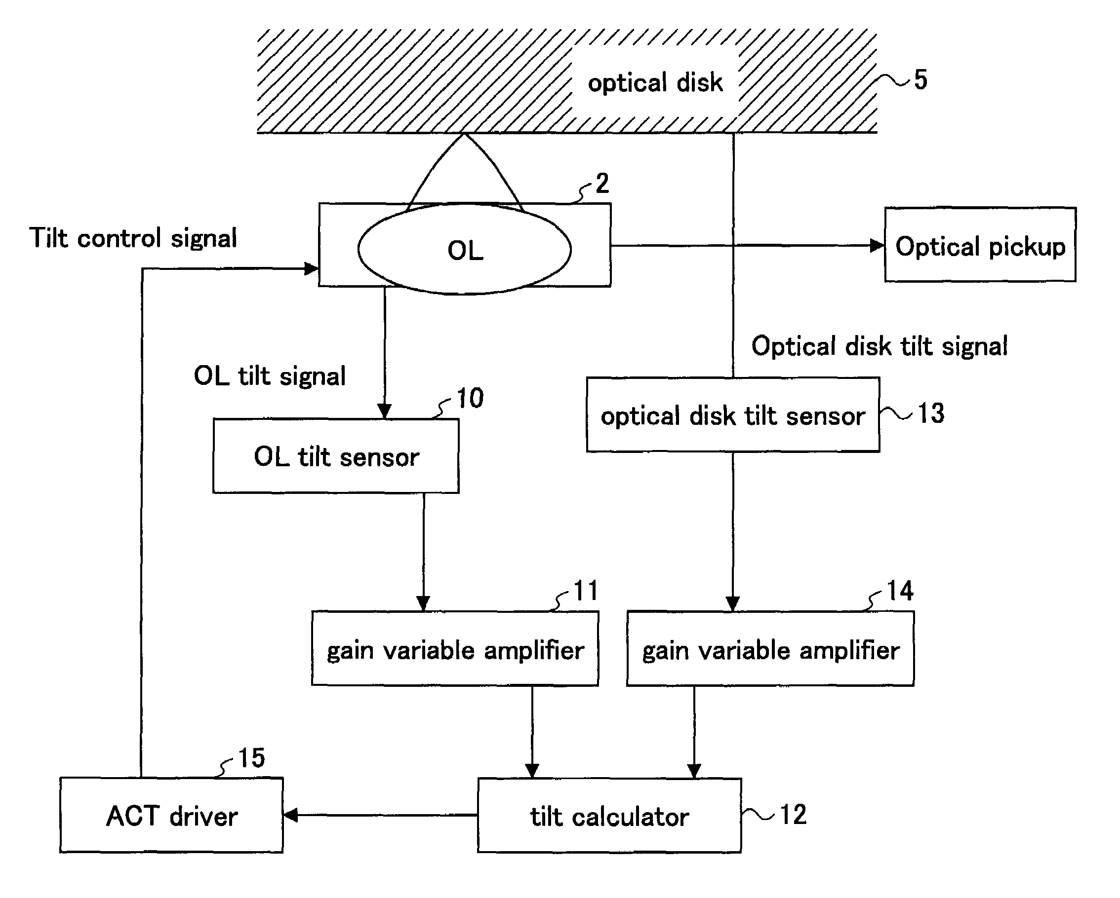
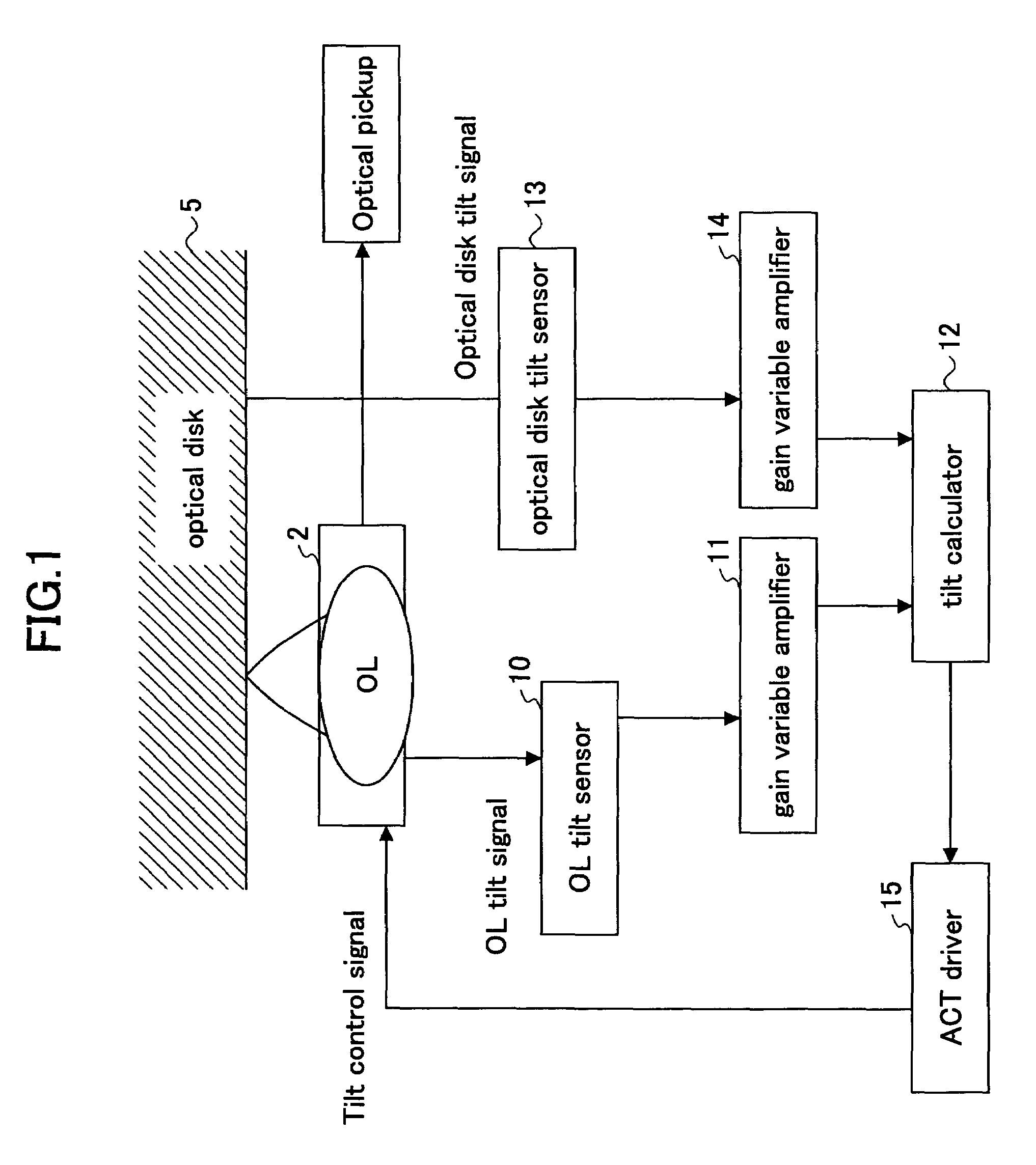
[0106]FIG. 1 is a block view schematically illustrating a configuration of an optical disk tilt compensation device according to the present invention.

[0107]As show in FIG. 1, an object lens (OL) 2 is fixed on an actuator (ACT), and can be adjusted in a radial tilt direction and a tangential tilt direction by applying an external signal. An object lens tilt sensor 10 detects a tilt of the object lens 2 in the radial direction and the tangential direction, separately, and detected tilt is input to a tilt calculator 12 through a gain variable amplifier 11, which serves as the “gain variable unit” in the claims.

[0108]The tilt of the optical disk 5 is detected by an optical disk tilt sensor 13 in the radial direction and the tangential direction, separately, and is input to the tilt calculator 12 through a gain variable amplifier 14. The tilt calculator 12 calculates the desired tilt of the object lens 2 from the detected tilt of the object lens 2 and the detected tilt of the optical di...

second embodiment

[0122]FIG. 5 is a block view schematically illustrating a first example of a configuration of an optical disk tilt compensation device according to the present invention.

[0123]As show in FIG. 5, from a signal component detected by a not-illustrated detector is provided in an optical pickup, a medium discriminator 16 discriminates the type of the optical disk 5. Based on the discrimination results, the variable gains of the gain variable amplifier 14 and the gain variable amplifier 11 can be determined.

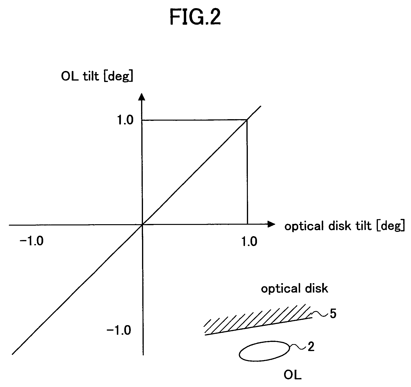
[0124]In the optical disk tilt compensation device of this example, the object lens (OL) 2 attached to an actuator (ACT) can support several wavelengths. For example, a light beam for a CD can be corrected as shown in FIG. 2, a light beam for a DVD can be corrected as shown in FIG. 3, and depending on the wavelength to be used, the correction is different. Because the gains of the gain variable amplifier 14 and the gain variable amplifier 11 can arbitrarily changed, it is possible to s...

third embodiment

[0207]In the present invention, the optical disk 5 is held in a cartridge 25 serving as a protection case. The optical disk 5 is inserted into the information recording and reproducing apparatus 20 from an insertion opening 22 along a “disk insertion” arrow, is driven to rotate by a spindle motor 23, and data therein is recorded, reproduced, or deleted. It should be noted that it is not necessary that the optical disk 5 be held in the cartridge 25, but can be held without the cartridge 25.

[0208]The information recording and reproducing apparatus 20 according to the third embodiment of the present invention includes the optical disk tilt compensation devices as described above to record and reproduce data in the optical disk 5. Because of the optical disk tilt compensation devices as described above are used, it is possible to reduce the margin of the tilt of the optical disk 5. For example, the unused margin can be used in high precision design of optical lenses supporting three wav...


PUM

PropertyMeasurementUnit
wavelengthaaaaaaaaaa
diameteraaaaaaaaaa
thicknessaaaaaaaaaa

Abstract

An optical recording medium tilt compensation device having a tilt compensation unit is disclosed that is able to compensate for a tilt error in servo control when recording or reproducing data in an optical recording medium. The optical recording medium tilt compensation device includes an object lens that condenses light from a light source on a recording surface of an optical recording medium; an object lens tilt actuator that controls a tilt of the object lens; an object lens tilt sensor that detects a tilt of the object lens; an optical recording medium tilt sensor that detects a tilt of the optical recording medium; a control unit that controls the tilt of the object lens in accordance with a tilt value from the optical recording medium tilt sensor so that an aberration of the spot condensed on the recording surface is minimum by driving the object lens tilt actuator; a gain variable unit that changes the magnitude of an output signal from the object lens tilt sensor or the optical recording medium tilt sensor.

Description

CROSS-REFERENCE TO RELATED APPLICATION[0001]This application is a U.S. continuation application filed under 35 USC 111(a) claiming benefit under 35 USC 120 and 365(c) of PCT application JP2004 / 011929, filed on Sep. 18, 2004, which claims priority to Japanese patent applications No. 2003-326428 filed on Sep. 18, 2003, and No. 2004-030108 filed on Feb. 6, 2004. The foregoing applications are hereby incorporated herein by reference.BACKGROUND OF THE INVENTION[0002]1. Field of the Invention[0003]The present invention particularly relates to an optical recording medium tilt compensation device having a tilt compensation unit able to compensate for a tilt error in servo control used when recording or reproducing data in an optical recording medium, a tilt compensation method, and an optical information recording apparatus using this method.[0004]2. Description of the Related Art[0005]A well known data recording method involves recording data on or reproducing data from an optical recordin...

Claims


Application Information

Patent Timeline
Patent Type & Authority Patents(United States)
IPC IPC(8): G11B15/62G11B17/32G11B5/58G11B7/095
CPCG11B7/0956
Inventor KAWASAKI, TOSHIYUKIHIRAI, HIDEAKI
Owner RICOH KK
Why Eureka
Try Eureka