Zoom lens

a zoom lens and lens body technology, applied in the field of zoom lenses, can solve the problems of difficulty in achieving size and cost reductions, and achieve the effects of suppressing an increase in the thickness of the lens, expanding the range of glass materials, and increasing the correction effect of aberrations

Active Publication Date: 2005-06-23
KONICA MINOLTA OPTO
View PDF2 Cites 21 Cited by
  • Summary
  • Abstract
  • Description
  • Claims
  • Application Information

AI Technical Summary

Benefits of technology

[0069] According to aspect (30), in the zoom lens described in aspect (29), a glass spherical lens and an aspherical resin are combined to expand the range of choice of glass materials and increase the correction effects for aberrations as compared with a glass mold aspherical lens. Note that the compound lens is formed by providing a thin aspherical resin layer on a glass matrix surface lens, and hence is regarded as a single lens.
[0070] According to aspects (31) and (32), the lens described in aspect (31) is defined to satisfy conditional expression [11] to be described later, and the lens described in aspect (32) is defined to satisfy conditional expression [12] to be described later. A compact structure is realized by suppressing an increase in the thickness of the lens in the optical axis direction while maintaining various kinds of performance.
[0071] According to aspect (33), when the magnification is to be changed from the wide angle end to the telephoto end, at least the first and third lens groups move to the object side, and the second lens group moves in the optical axis direction so as to increase the gap between the first lens group and the second lens group and decrease the gap between the second lens group and the third lens group. Therefore, the same zoom ratio as that of a zoom lens of the type that changes the magnification only by moving the second lens group can be realized by the second lens group having a lower power and with a smaller moving amount. This makes it possible to attain both compactness and good optical performance. In addition, since the first lens group can be placed at a position relatively close to the entrance pupil on the wide angle end, the front-element diameter can be set to be relatively small.
[0072] According to aspect (34), the magnification is changed from the wide angle end to the telephoto end by integrally moving the first and third lens groups. This further simplifies the lens barrel structure and driving mechanism, thus achieving ease of use.

Problems solved by technology

As described above, for example, too many lenses makes it difficult to achieve reductions in size and cost.

Method used


Image

  • Zoom lens
  • Zoom lens
  • Zoom lens

Examples


first embodiment

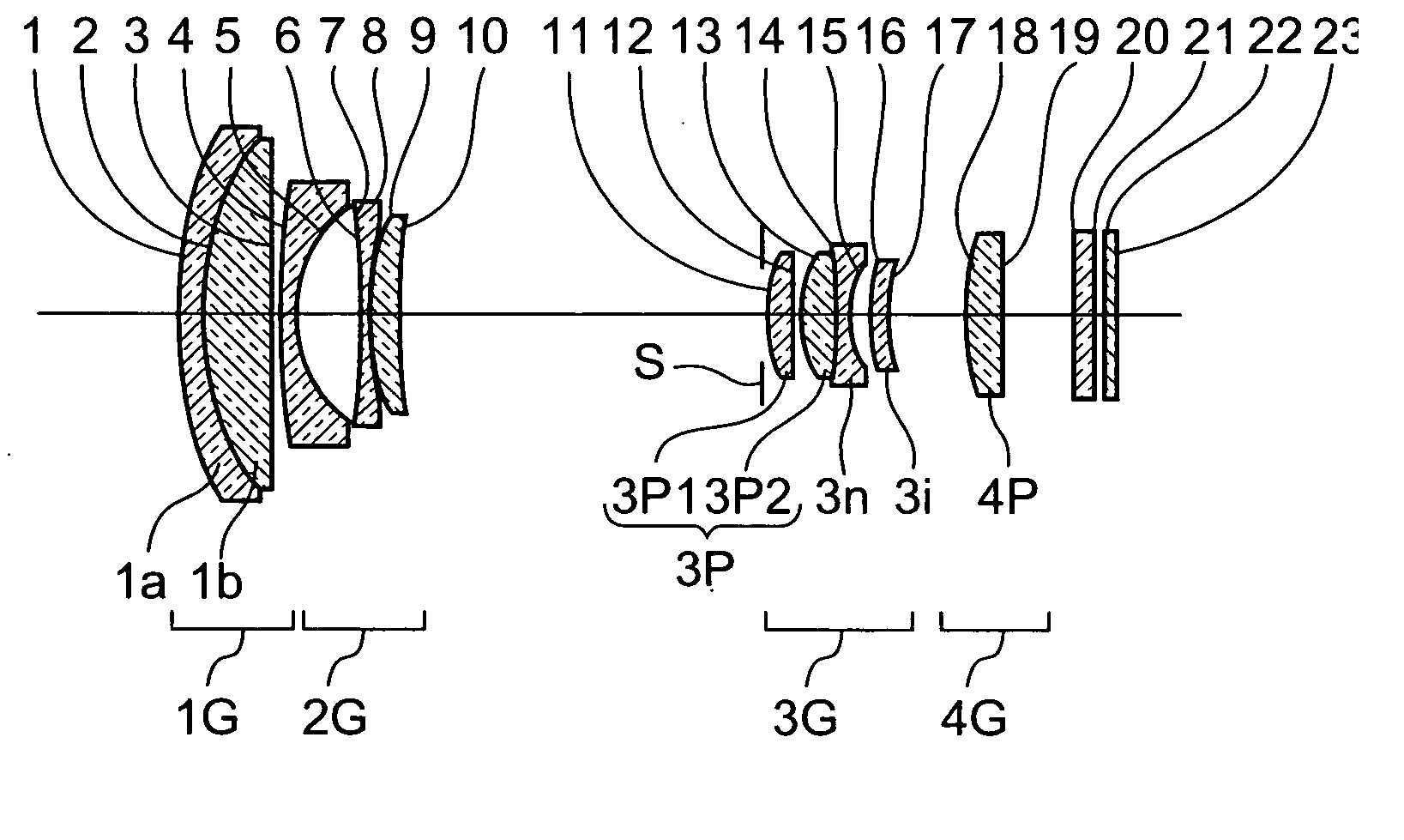
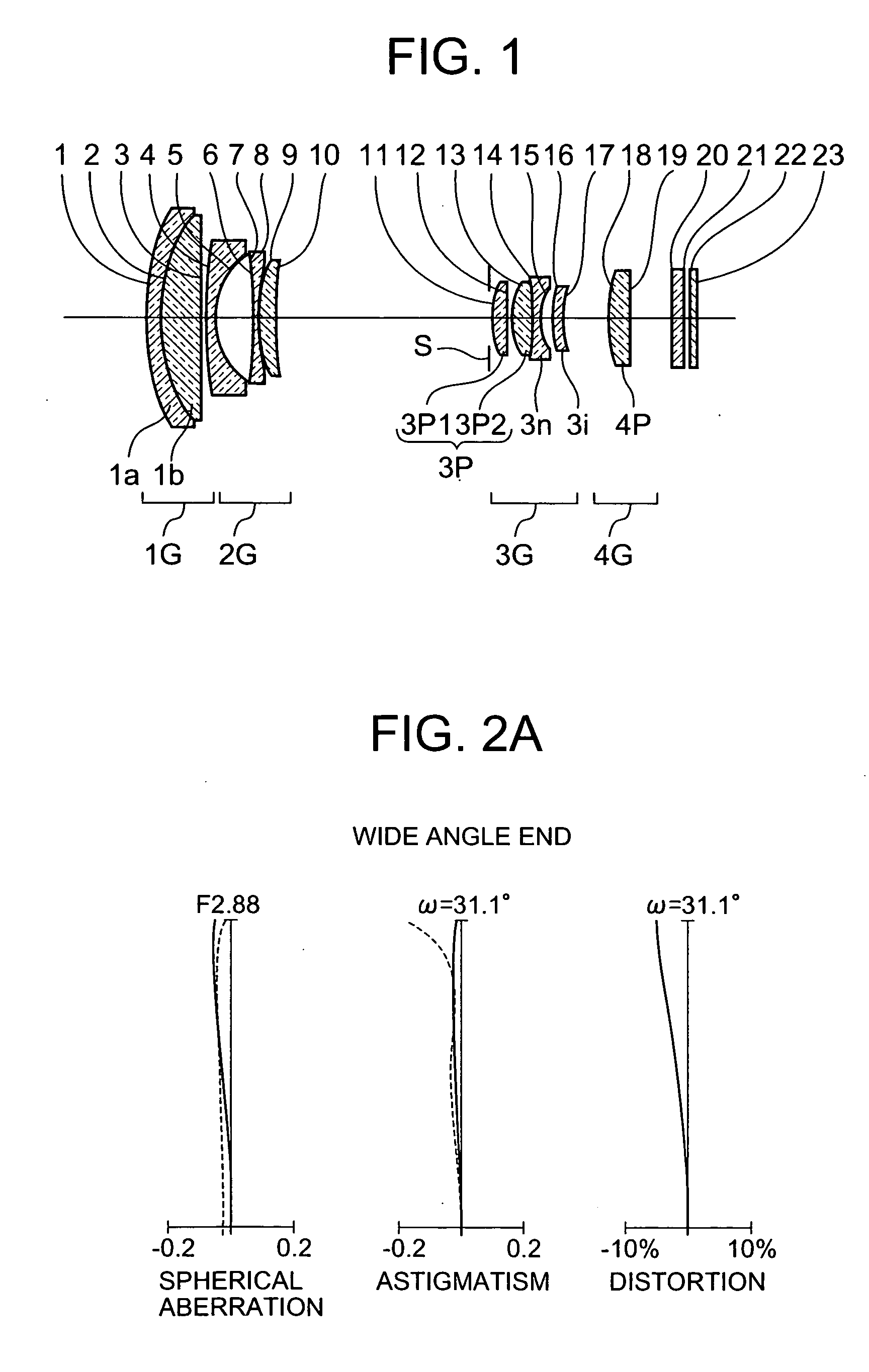
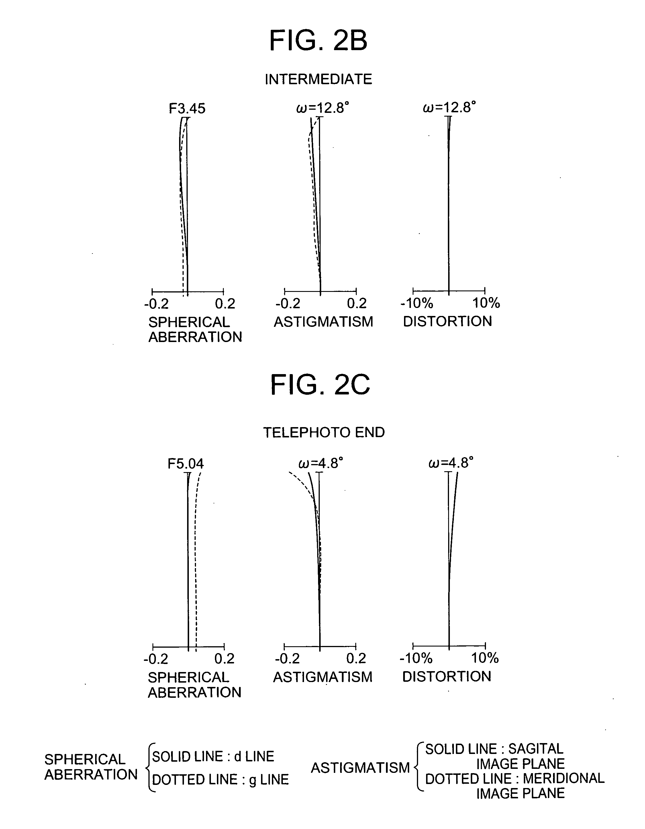
[0110] The first embodiment is associated with aspects (1) to (37). FIG. 1 is a sectional view of a zoom lens according to the first embodiment. Referring to FIG. 1, the zoom lens is a four group lens including positive, negative, positive, and positive lens groups arranged from the object side. A first lens group 1G includes a negative lens 1a and positive lens 1b. A third lens group 3G includes a lens 3p1, lens 3p2, lens 3n, and lens 3i. A fourth lens group 4G includes a lens 4p. An aperture stop S is placed in the air gap between a second lens group 2G and the third lens group 3G. When the magnification is to be changed from the wide angle end to the telephoto end, the first lens group 1G and third lens group 3G integrally move. Tables 1 and 2 show lens data.

[0111] Note that the sixth to eighth surfaces in the second lens group 2G constitute a hybrid aspherical lens, the lens 3i (16th and 17th surfaces) in the third lens group 3G is a plastic aspherical lens, and the lens 4p (18...

second embodiment

[0114] The second embodiment is associated with aspects (1) to (37). FIG. 3 is a sectional view of a zoom lens according to the second embodiment. Referring to FIG. 3, the zoom lens is a four group lens including positive, negative, positive, and positive lens groups arranged from the object side. A first lens group 1G includes a negative lens 1a and positive lens 1b. A third lens group 3G includes a lens 3p1, lens 3p2, lens 3n, and lens 3i. A fourth lens group 4G includes a lens 4p.

[0115] An aperture stop S is placed in the air gap between a second lens group 2G and the third lens group 3G. When the magnification is to be changed from the wide angle end to the telephoto end, the first lens group 1G and third lens group 3G integrally move.

[0116] Note that the sixth to eighth surfaces in the second lens group 2G constitute a hybrid aspherical lens, the lens 3i (16th and 17th surfaces) in the third lens group 3G is a plastic aspherical lens, and the lens 4p (18th and 19th surfaces) ...

third embodiment

[0120] The third embodiment is associated with aspects (1) to (33) and (35) to (37). FIG. 5 is a sectional view of a zoom lens according to the third embodiment. Referring to FIG. 5, the zoom lens is a four group lens including positive, negative, positive, and positive lens groups arranged from the object side. A first lens group 1G includes a negative lens 1a and positive lens 1b. A third lens group 3G includes a lens 3p1, lens 3p2, lens 3n, and lens 3i. A fourth lens group 4G includes a lens 4p. An aperture stop S is placed in the air gap between a second lens group 2G and the third lens group 3G. When the magnification is to be changed from the wide angle end to the telephoto end, the first lens group 1G and third lens group 3G move. The second lens group G2 moves in the optical axis direction so as to increase the gap between the first lens group 1G and the second lens group 2G and decrease the gap between the second lens group 2G and the third lens group 3G.

[0121] Note that t...


PUM


Abstract

In a zoom lens of this invention, a first lens group having a positive refraction power, a second lens group having a negative refraction power, a third lens group having a positive refraction power, and a fourth lens group having a positive refraction power are arranged sequentially from an object side toward an image side, and the magnification is changed from the wide angle end of the zoom lens to the telephoto end thereof, and vice versa, by varying each distance between each pair of the first to the fourth lens groups. The first lens group includes a positive lens and a negative lens. The third lens group includes at least a positive lens and a negative lens arranged sequentially from the object side toward the image side. At least the positive lens of the third lens group is a spherical lens. That lens of the third lens group which is located closest to the image side is a lens having an aspherical surface on at least one surface thereof.

Description

[0001] This application is based upon and claims priority under 35 U.S.C.§ 119 from the Japanese Patent Application No. 2003-419261 filed Dec. 17, 2003, at least entire content are incorporated herein by reference. BACKGROUND OF THE INVENTION [0002] 1. Field of the Invention [0003] The present invention relates to a zoom lens and, more particularly, to a zoom lens used for, for example, a digital camera using a CCD. [0004] 2. Description of the Prior Art [0005] Conventionally, as zoom lenses in this field, the zoom lenses disclosed in Japanese Unexamined Patent Publication Nos. 2002-244039 and 2002-006216 have been available. [0006] Japanese Unexamined Patent Publication No. 2002-244039 discloses a zoom lens in which a first lens group having a positive focal length, a second lens group having a negative focal length, and third, fourth, and fifth lens groups each having a positive focal length are arranged from the object side toward the image side, and an aperture stop is provided ...

Claims


Application Information

Patent Timeline
Patent Type & Authority Applications(United States)
IPC IPC(8): G02B15/20G02B13/18G02B15/173
CPCG02B15/173G02B15/144113
Inventor YAMASHITA, ATSUSHI
Owner KONICA MINOLTA OPTO
Why Eureka
Try Eureka