Mapping pulse propagation

a pulse propagation and mapping technology, applied in the field of mapping pulse propagation, can solve the problem of unknown phase changes within the duration of the shutter scan

Pending Publication Date: 2022-10-13
NOKIA TECHNOLOGLES OY
View PDF0 Cites 0 Cited by
  • Summary
  • Abstract
  • Description
  • Claims
  • Application Information

AI Technical Summary

Problems solved by technology

Additionally, if a rolling shutter camera is used, unknown pha

Method used


Image

  • Mapping pulse propagation
  • Mapping pulse propagation
  • Mapping pulse propagation

Examples


Embodiment Construction

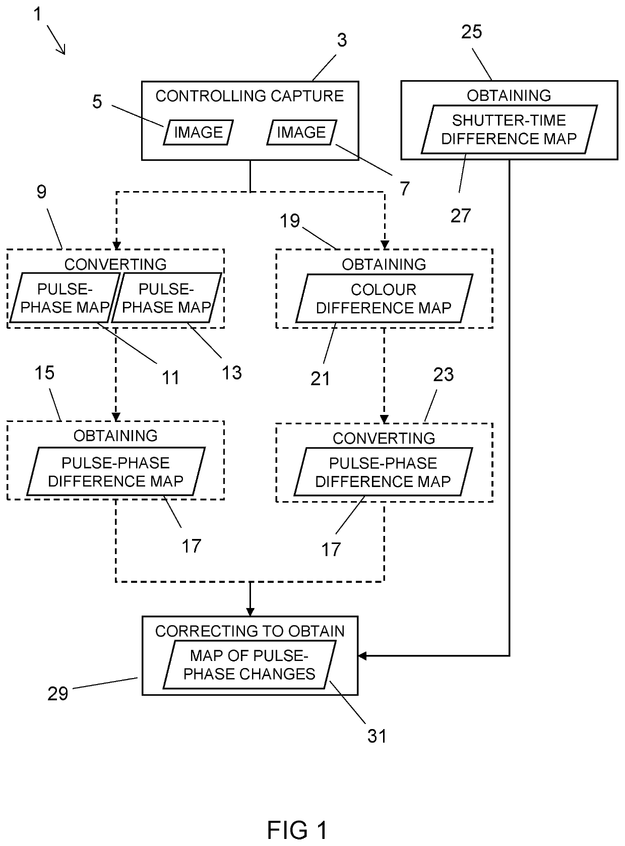
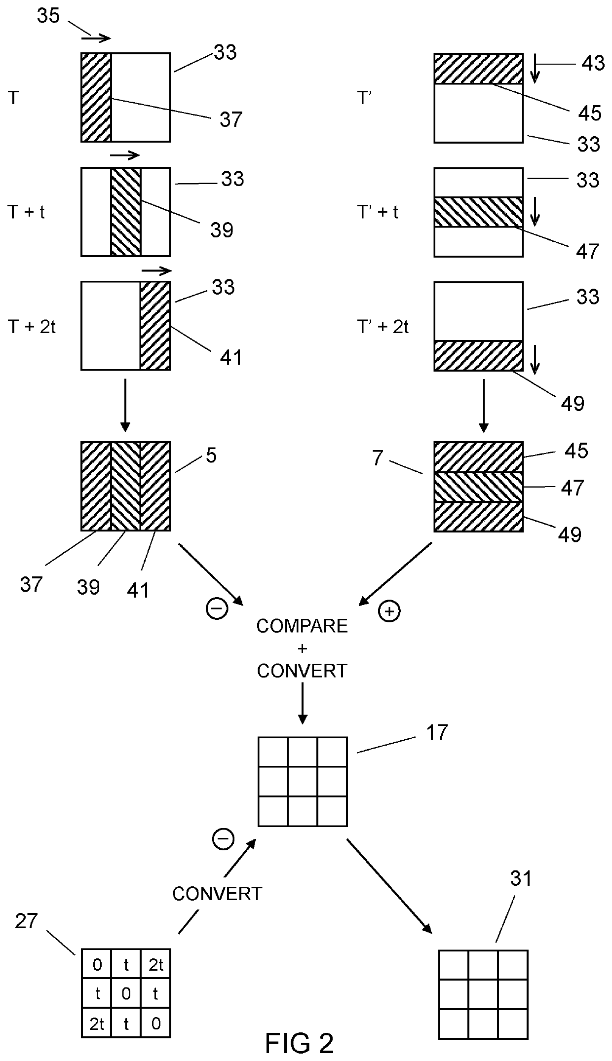
[0033]Examples of the disclosure relate to using images captured with different shutter scanning directions to resolve information about the pulse's propagation to within a duration of a shutter scan. The temporal resolution of information about the pulse's propagation is therefore dependent upon shutter scanning speed. Higher temporal resolution can be achieved by increasing the shutter scanning speed.

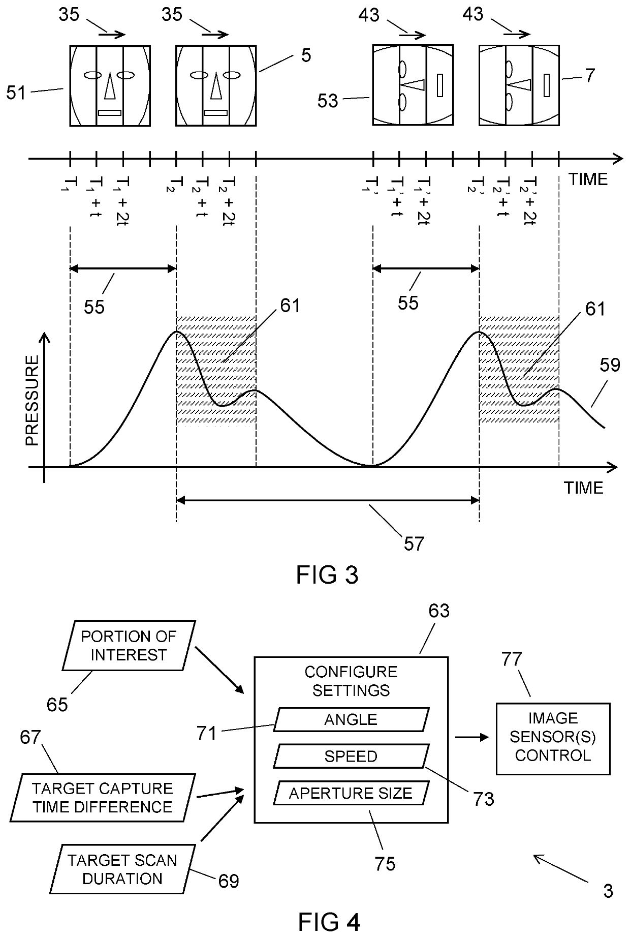
[0034]In some but not necessarily all examples described herein, the pulse is a blood pressure pulse in which the blood pressure rises and falls, responding to the cardiac cycle. Accordingly, the pulse is a periodic function, having a periodic waveform, and a phase of the pulse (pulse-phase) represents which stage of the cardiac cycle the blood pressure at a given location is responding to.

[0035]In some but not necessarily all examples described herein, the area through which the pulse's propagation is observed is a body surface, for example, a face or a palm, being formed of tissue a...


PUM


Abstract

Examples of the disclosure relate to at least apparatus, methods, and computer programs, configured to control capture of two images of an area, across which a pulse propagates, using different shutter scanning directions. Either the images are converted into pulse-phase maps of the area and a pulse-phase difference map obtained which identifies differences between the pulse-phase maps of the area, or a colour difference map is obtained which identifies differences between the two images and the colour difference map is converted into a pulse-phase difference map. A shutter-time difference map is obtained which identifies differences between capture times of corresponding locations in the two images. Using the shutter-time difference map, the pulse-phase difference map is corrected to obtain a map of pulse-phase changes which have occurred over a duration of a shutter scan.

Description

TECHNOLOGICAL FIELD[0001]Embodiments of the present disclosure relate to mapping pulse propagation. Some relate to mapping the pulse propagation across an area which occurs within a duration of a shutter scan.BACKGROUND[0002]The propagation of a pulse across an area can be measured using measurements of the phase of the pulse at least at two different times. The ability to resolve the phase changes is limited by the frame rate of the camera. Additionally, if a rolling shutter camera is used, unknown phase changes will occur within the duration of the shutter scan.BRIEF SUMMARY[0003]According to various, but not necessarily all, embodiments there is provided an apparatus comprising means for: controlling capture of two images of an area, across which a pulse propagates, using different shutter scanning directions; converting the images into pulse-phase maps of the area; obtaining a pulse-phase difference map identifying differences between the pulse-phase maps of the area; obtaining ...

Claims


Application Information

Patent Timeline
IPC IPC(8): H04N5/235H04N5/225G06T7/90G06V10/74
CPCH04N5/2353H04N5/2258G06T7/90H04N5/2259G06V10/74G06T2207/10024G06T2207/10144G06T2207/30196A61B5/02416H04N2201/0079H04N1/00068H04N1/00042H04N1/00005A61B5/02108A61B5/0077G06T7/254G06T2207/30048G06T2207/30104G06V10/56G06V40/16G06V10/12H04N23/73H04N23/45H04N23/58
Inventor WRIGHT, CHRISTOPHERCRONIN, HARRYCATTON, PHILSCHNABEL, WILLIAM
Owner NOKIA TECHNOLOGLES OY
Why Eureka
Try Eureka