Air-conditioning control system and air-conditioning equipment
a control system and air-conditioning technology, applied in the direction of space heating and ventilation control systems, lighting and heating apparatus, heating types, etc., can solve the problems of reducing the confidence in the air-conditioning control system, lowering and reducing the confidence in the air-conditioning equipmen
- Summary
- Abstract
- Description
- Claims
- Application Information
AI Technical Summary
Benefits of technology
Problems solved by technology
Method used
Image

Examples
first embodiment
[0063]Description will be made below on an embodiment where the present disclosure is embodied with reference to the drawings. The air-conditioning control system according to the present embodiment is embodied as air-conditioning equipment provided in a building. It should be noted that “air conditioning” according to the present embodiment means adjusting a state of air, such as temperature, moisture, and cleanliness, by cooling / heating, dehumidification / humidification, and ventilation.
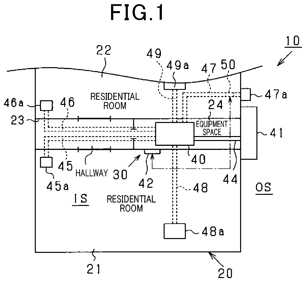
[0064]As illustrated in FIG. 1, air-conditioning equipment 30, which is provided in a building 10, includes an air conditioner 40 installed indoors (an equipment space 24), an exterior unit 41 installed outdoors, an air-conditioning controller 42 that controls the air conditioner 40 and the exterior unit 41, a pipe for heat exchange that connects the air conditioner 40 and the exterior unit 41, intake ducts 45 to 47 through which air for air conditioning is to be taken into the air conditioner 40, s...
second embodiment
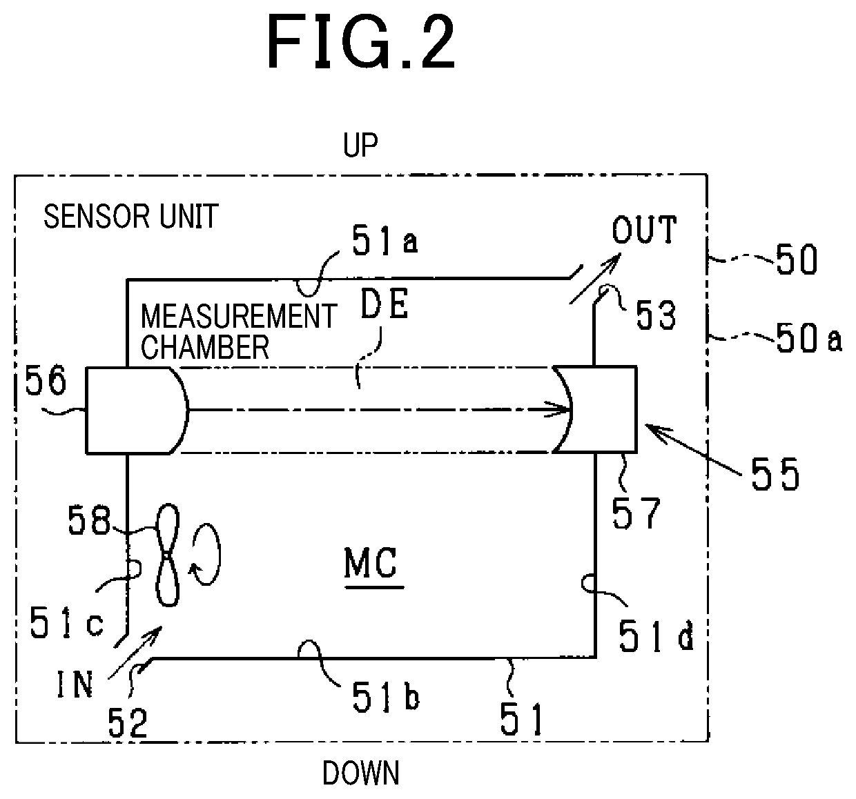
[0092]In the above-described first embodiment, the fan 58 is stopped during preparation for calibration, thereby reducing the entry of new particles into the measurement chamber MC. However, in a configuration where the inlet 52 is always open, particles, the amount of which is small, would still enter the measurement chamber MC as long as outside air passes through the intake duct 47. In consideration of such circumstances, the special stop mode is set as the ventilation mode when the fan 58 is stopped, thereby enhancing a function to reduce the entry of new particles into the measurement chamber MC in the first embodiment. The present embodiment is different from the first embodiment in a configuration for reducing the entry of new particles during preparation for calibration. Referring to FIG. 8A and FIG. 8B, description will be made below on a characteristic configuration of the present embodiment with a focus on a difference from the first embodiment.
[0093]A sensor unit 50A acc...
third embodiment
[0097]The sensor unit 50A according to the above-described second embodiment is configured to reduce the entry of air and particles thorough the intake duct 47 by closing the inlet 52 with the shutter 61A. In the present embodiment, the shutter 61A is replaced with a movable filter 61X (corresponding to the “moving body”) that does not let particles through while letting air through (see FIG. 8A and FIG. 8B).
[0098]In starting the preparation for calibration, the filter 61X is placed at a position for covering the inlet 52, thereby preventing the entry of new particles through the inlet 52. Further, the operation of the fan 58 is continued even during the preparation for calibration. With the operation of the fan 58 continued, the air within the measurement chamber MC is caused to flow out through the outlet53 while air is caused to enter from the intake duct 47 through the inlet 52. That is to say, the ventilation of the measurement chamber MC is continued. The ventilation causes th...
PUM
 Abstract
Description
Claims
Application Information
 - R&D
- Intellectual Property
- Life Sciences
- Materials
- Tech Scout
- Unparalleled Data Quality
- Higher Quality Content
- 60% Fewer Hallucinations
Browse by: Latest US Patents, China's latest patents, Technical Efficacy Thesaurus, Application Domain, Technology Topic, Popular Technical Reports.
© 2025 PatSnap. All rights reserved.Legal|Privacy policy|Modern Slavery Act Transparency Statement|Sitemap|About US| Contact US: help@patsnap.com