Modulated flame gas flow rates in flame-based detectors

a flame gas flow rate and detector technology, applied in the field of flame gas mass flow rate modulation to a flame-based detector, can solve the problems of reducing detector performance, destabilizing or even suffocating the flame, and less than optimal detector response to the analyte, so as to save time for a practitioner, enhance chromatographic separation, and maintain confidence in the accuracy of results

Active Publication Date: 2017-04-18
WATERS TECH CORP
View PDF12 Cites 0 Cited by
  • Summary
  • Abstract
  • Description
  • Claims
  • Application Information

AI Technical Summary

Benefits of technology

[0008]When conducting a chromatographic separation which employs density programming and flame-based detection, the response of the flame-based detector can be optimized for one mass flow rate of the mobile phase. At other mobile phase mass flow rates, however, detector performance can suffer reduced sensitivity. This varying detector response can also reduce confidence in the results when quantifying individual analytes of a chromatographic separation. In general, the present disclosure relates to methods that can maintain optimum detector performance throughout an entire density-programmed chromatographic separation. This normalization of response can help increase confidence in the quantitative results of a chromatographic separation by ensuring that all regions of a chromatogram accurately reflect the mass flow rate of carbon (i.e., analyte) entering a flame-based detector at a given time point. Automated management of flame gas flow rates (e.g., hydrogen and oxygen) can be provided by feedback from system parameters, such as pressure, temperature, or density, or from the mass flow rate of mobile phase fluid directed to the detector in the chromatographic system. Accordingly, the present technology substantially eliminates and / or reduces variability in the flame-based detector response when performing density gradient separations.
[0026]The present technology provides a number of benefits and advantages over current methods and apparatus. For instance, the present technology may allow a user to employ a density gradient to enhance a chromatographic separation while still maintaining an optimized flame in a flame-based detector, and thus maintain confidence in the accuracy of results. In addition, the present technology may enable the sensitivity of a flame-based detector to be optimized over the course of an entire chromatographic run, instead of a portion of the run. By automatically optimizing the amount of combustion gas entering a flame-based detector, the present technology can save time for a practitioner by obviating the need to re-optimize combustion gas flow rates. Further, the technology may help resolve the issue of changing detector response factors over the course of a chromatographic separation with a changing mobile phase mass flow rate (e.g., in density programmed separations). The technology ensures uniformity of response for each compound eluted under a dynamic mobile phase mass flow rate separation (e.g., density programmed conditions). The above advantages and aspects can be more clearly understood in light of the drawings and detailed description outlined below.

Problems solved by technology

For example, when the mass flow rate of mobile phase fluid (e.g., carbon dioxide) entering a flame-based detector is increased, it can result in less than optimal detector response to the analyte.
In some cases, it can destabilize or even suffocate and extinguish the flame.
At other mobile phase mass flow rates, however, detector performance can suffer reduced sensitivity.
This varying detector response can also reduce confidence in the results when quantifying individual analytes of a chromatographic separation.

Method used


Image

  • Modulated flame gas flow rates in flame-based detectors
  • Modulated flame gas flow rates in flame-based detectors
  • Modulated flame gas flow rates in flame-based detectors

Examples


example 1

Determining a Correlation Between Mobile Phase Mass Flow Rate to Combustion Gas Flow Rate

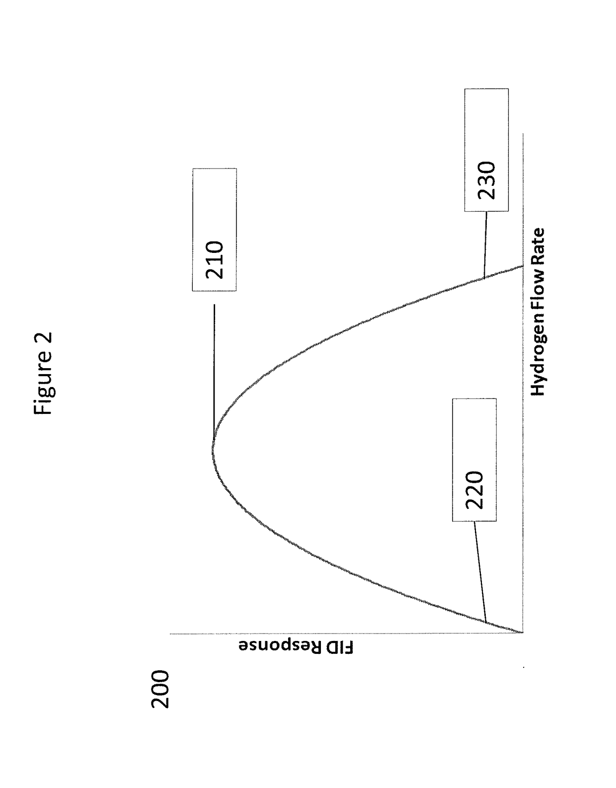
[0100]A CO2-based chromatography system with SFC capabilities (e.g., a UPC2 chromatography system; commercially available from Waters Technologies Corporation, Milford, Mass., USA) was equipped with a flame ionization detector. Compressed carbon dioxide was used as the mobile phase. The flow rate of carbon dioxide (mL / min) as a decompressed gas entering the detector was measured at four different values, shown below in Table 1. The optimal flow rate of hydrogen gas (mL / min) necessary for optimal response at each value of decompressed carbon dioxide was determined empirically by preparing a calibration curve of analyte response to hydrogen flow rate. The results are given in Table 1 below:

[0101]

TABLE 1Optimal Hydrogen Gas Flow Rate as a Function ofDecompressed Carbon Dioxide Flow RateDecompressed CO2 flow rate atRequired H2 flow rate for optimalthe FID (mL / min)response (mL / min)14.23937.8551009020...

example 2

Adjustment of Combustion Gas Flow Rate Based on Measured Mobile Phase Mass Flow Rate

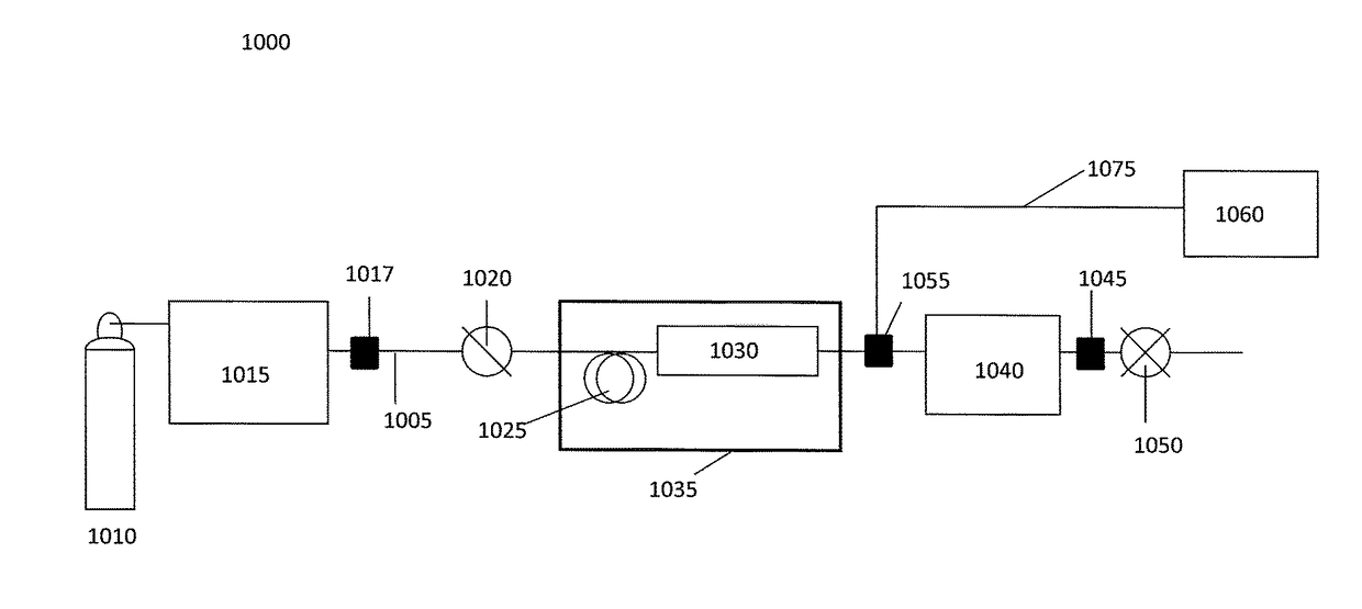
[0104]A chromatographic system having an adjustable flow rate of a carbon dioxide (CO2) mobile phase is provided. The chromatographic system is in fluid communication with a flame ionization detector, which is equipped with a split-flow interface (about 25:1 initial split ratio). The chromatographic system is situated upstream of the detector.

[0105]Pressure, temperature and flow rate data related to the carbon dioxide mobile phase are collected via sensors attached to the chromatographic system and relayed in real time to a microcontroller in electronic communication with the sensors. The data provided by these sensors is used to calculate the mass flow rate of CO2 through the chromatographic column. Since the density of the CO2 varies considerably throughout the system, the value at the pump head is used to determine mass flow. The carbon dioxide mobile phase is flowed at a rate of 0.8 mL / min with a...

example 3

Adjustment of Combustion Gas Flow Rate Based on Pre-Determined Mobile Phase Mass Flow Rate

[0110]A chromatographic system having an adjustable flow rate of a carbon dioxide mobile phase is provided. The chromatographic system is in fluid communication with a flame ionization detector, which is equipped with a split-flow interface (about 25:1 split ratio). The chromatographic system is situated upstream of the detector.

[0111]A density gradient for the CO2 mobile phase is pre-determined before beginning the chromatographic separation. The density gradient is selected based on prior separation results or theoretical considerations. The desired pressure, temperature and flow rate data related to the carbon dioxide mobile phase at every time point in the separation are input into a computer, which is converted to a theoretical mass flow rate of carbon dioxide by the computer.

[0112]During the course of the separation, data related to pressure, temperature and flow rate are also collected v...


PUM

PropertyMeasurementUnit
critical pointaaaaaaaaaa
mass flow rateaaaaaaaaaa

Abstract

Methods and apparatus for the modulation of flame gas stoichiometry to a flame-based detector for use in chromatographic separations are presented. As the total mass flow rate of mobile phase entering the flame-based detector changes (e.g., as a result of density programming in the separation), the mass flow rate of combustion gases to the detector are altered in proportion to the amount of mobile phase entering the detector. As a result, flame stability and sensitivity of the detector can be maintained by the methods and apparatus of the present disclosure.

Description

CROSS-REFERENCE TO RELATED APPLICATIONS[0001]This application claims priority to and the benefit of U.S. Provisional Application No. 61 / 889,783 filed Oct. 11, 2013, and entitled “Modulated Flame Gas Flow Rates In Flame-Based Detectors” which is incorporated herein by reference in its entirety.TECHNICAL FIELD[0002]The present disclosure is directed to methods and related apparatus for the modulation of flame gas mass flow rates to a flame-based detector. In the context of density-programmed gradient chromatographic separations, for example, the technology provides for methods and related apparatus to adjust (e.g., increase or decrease) the mass flow rate of combustion gases (e.g., hydrogen and / or oxygen) to a flame-based detector in response to changes in the mass flow rate of a mobile phase fluid (e.g., carbon dioxide) entering the detector.BACKGROUND[0003]Flame-based detection is a common technique used in chromatography (e.g., gas chromatography) to detect analytes of interest (e....

Claims


Application Information

Patent Timeline
Patent Type & Authority Patents(United States)
IPC IPC(8): G01N7/00G01N30/68G01N33/00G01N30/38G01F1/76G01N1/28G01N30/32G01N1/00
CPCG01N30/38G01F1/76G01N1/28G01N30/68G01N33/0016G01N2001/002G01N2030/324Y02E20/32B01D15/10F23N5/00G01N30/62G01N2030/685
Inventor FOGWILL, MICHAEL O.MICHIENZI, JOSEPH D.MURPHY, JAMES P.
Owner WATERS TECH CORP
Why Eureka
Try Eureka