Method for forming a rib on a cannula for a tip protection device

a technology of tip protection device and cannula, which is applied in the direction of manufacturing tools, catheters, infusion needles, etc., can solve problems such as danger to medical personnel

Inactive Publication Date: 2000-01-11
MEDEX INC
View PDF27 Cites 57 Cited by
  • Summary
  • Abstract
  • Description
  • Claims
  • Application Information

AI Technical Summary

Problems solved by technology

It is of considerable concern for users of such devices that, if a means for disengaging the retaining elem...

Method used


Image

  • Method for forming a rib on a cannula for a tip protection device
  • Method for forming a rib on a cannula for a tip protection device
  • Method for forming a rib on a cannula for a tip protection device

Examples


Embodiment Construction

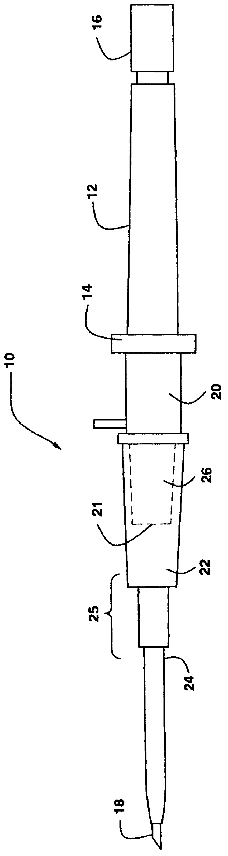
This invention relates to the field of hypodermic needles and most particularly to devices for inserting catheters into blood vessels. Referring now to the drawings, FIG. 1 shows a catheter insertion apparatus 10, having a safety cover 20. The apparatus 10, which is shown in a side view, includes a syringe body 12, with an annular ring 14 at the base thereof, and a standard slidable plunger element 16 which translates within the syringe body 12. A cannula 18 extends axially outward from the annular ring 14; the narrow hollow internal passage within the cannula 18 providing a connection from the internal volume of the syringe body 12 to the exterior through which fluids may flow.

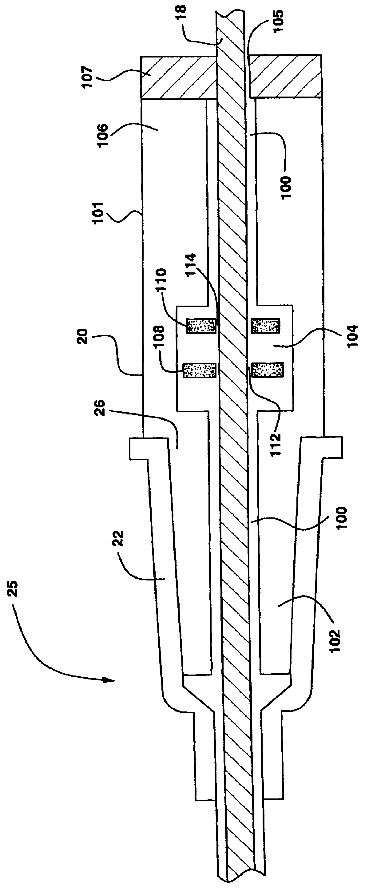
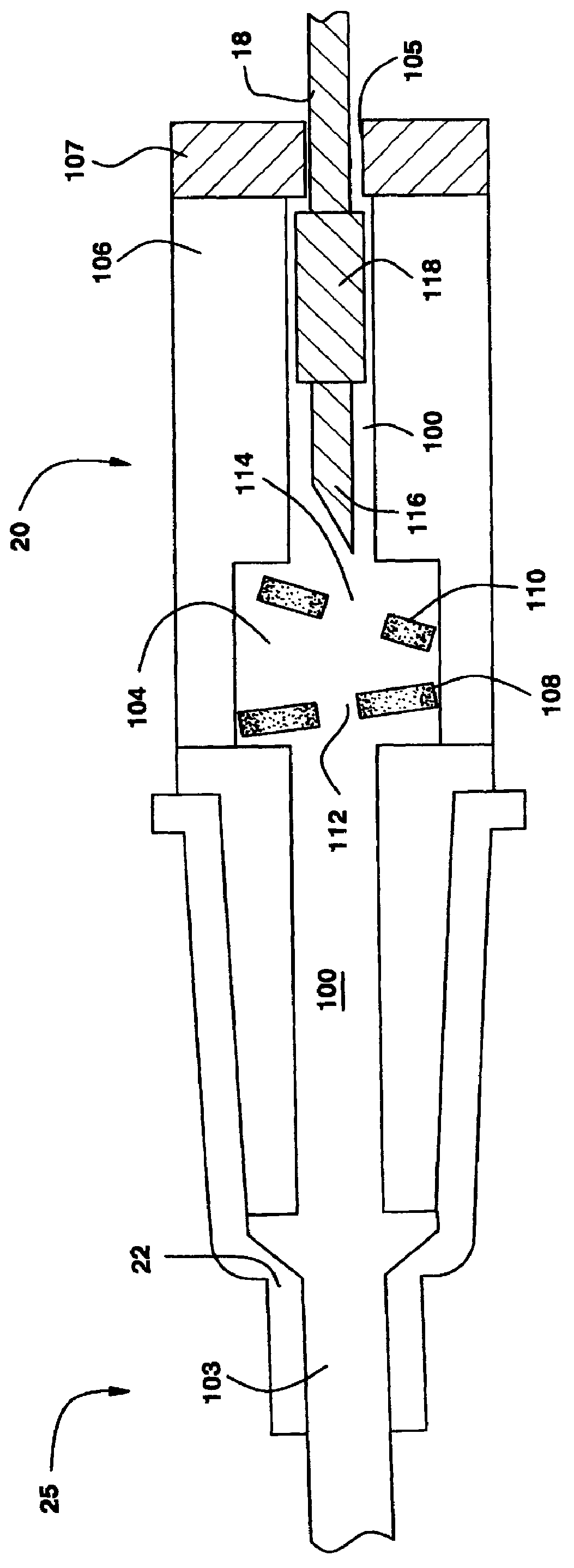
The cannula 18 extends outward from the annular ring 14 through a safety cover 20 which is constructed so that the cannula 18 may be inserted axially therethrough and so that the cannula 18 and safety cover 20 may be translated relative to each other. In the embodiment shown in FIG. 1, which is designed to in...


PUM

PropertyMeasurementUnit
Temperatureaaaaaaaaaa
Lengthaaaaaaaaaa
Diameteraaaaaaaaaa

Abstract

Methods for forming a rib on a cannula for cooperation with a safety cover which securably and reliably locks the tip of a cannula in an interior chamber within the safety cover. The cover comprises an elongate body having the interior chamber and an axial through hole which extends along the entire length of the body, through the interior chamber and through which the cannula is slidably received. Displacing elements are positioned within the interior chamber, each of which includes a hole for receiving the cannula therethrough, and which displaces upon retraction of the tip of the cannula, thereby preventing subsequent advancement of the cannula tip. The cannula includes a thickened rib adjacent to the tip, and the safety cover should correspondingly include an annular section in the rear portion thereof. The through hole extending through the rear portion has a diameter which is smaller than the thickened rib of the cannula whereby the cannula tip may not be retracted from the safety cover. The rib is formed by a thermal method in which a sleeve is heated to expand its inside diameter to allow the sleeve to be slid onto the cannula. The sleeve is then cooled to room temperature so that the inside diameter contracts to attach the sleeve to the cannula. In another method, a sleeve is placed on the cannula and crimped at the desired location.

Description

1. Field of the InventionThe present invention relates generally to stick prevention apparatus for protecting medical personnel from injury. More particularly, the present invention relates to tip protection devices having internal elements which prevent a retracted needle from reinserting therethrough and a method for forming the elements.2. Description of Prior ArtMedical care of individuals in hospitals, clinics, and other health care facilities often includes the taking of blood samples, intravenous supplying of medication, and the introduction or removal of other fluids via cannulae, needles, or syringes. The present medical environment, in which there exist diseases, for example Acquired Immune Deficiency Syndrome, AIDS, for which there are no cures, and which are transmitted via blood to blood contact, has raised concerns relating to the potential for contaminated "needle sticks".A wide variety of devices have been provided in the prior art for prevention against accidental c...

Claims


Application Information

Patent Timeline
IPC IPC(8): A61M25/06A61M5/32A61M5/158A61M25/16B23P11/00B23P11/02
CPCA61M5/3273A61M25/0618A61M5/3243Y10T29/49865A61M2005/325A61M5/00
Inventor CHANG, JOSEPH J.CANNON, JULIAN
Owner MEDEX INC
Why Eureka
Try Eureka