Integrated fire and flight control system with automatic engine torque limiting

a flight control system and engine technology, applied in the field of rotary wing aircraft flight control systems, can solve problems such as damage or shorten the life of the engine, and achieve the effects of limiting the pilot's ability to demand more engine power, preventing over torque conditions, and reducing the collective access displacemen

Inactive Publication Date: 2000-01-11
SIKORSKY AIRCRAFT CORP
View PDF9 Cites 32 Cited by
  • Summary
  • Abstract
  • Description
  • Claims
  • Application Information

AI Technical Summary

Benefits of technology

The torque limiting function of the present IFFC system, when engaged, limits the pilot's ability in demanding more engine power than available during aggressive maneuvering of the aircraft. The sensed actual engine torque is compared to a preset upper torque limit that is a function of density altitude. The resulting difference signal represents a torque error signal which is modified through both proportional and interval gain paths and provided as a down collective modifying command signal to the f...

Problems solved by technology

Depending on ambient air density conditions, the Altitude Hold may place excessive torque demands ...

Method used


Image

  • Integrated fire and flight control system with automatic engine torque limiting
  • Integrated fire and flight control system with automatic engine torque limiting
  • Integrated fire and flight control system with automatic engine torque limiting

Examples


Embodiment Construction

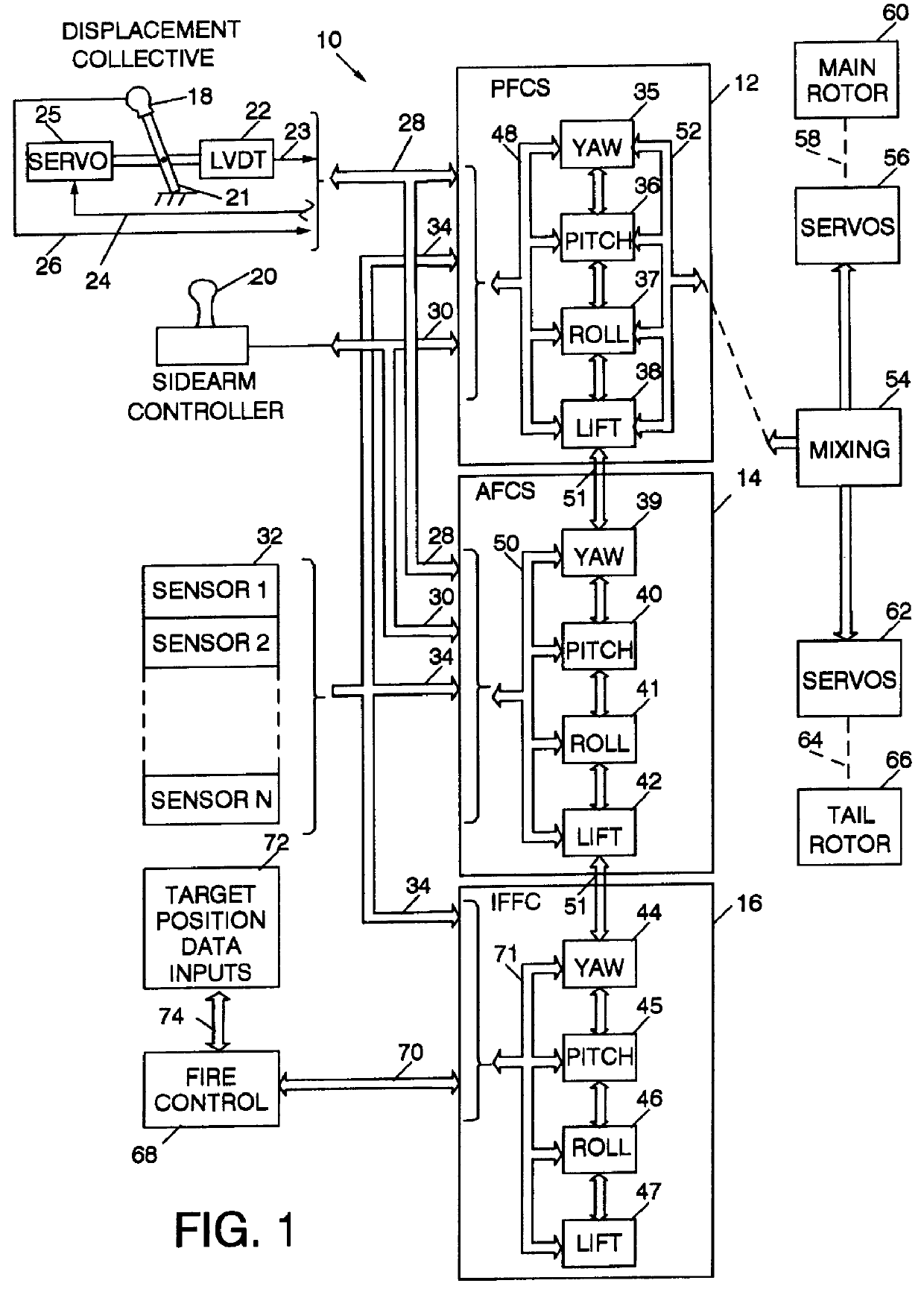
Referring to FIG. 1, the integrated fire and flight control (IFFC) system 10 of the present invention includes a primary flight control system (PFCS) 12, an automatic flight control system (AFCS) 14, and an IFFC 16. The PFCS 12 and AFCS 14 each receive displacement command signals from the pilot operated displacement collective stick 18 and force command signals from a four axis side arm controller 20. The displacement stick is typically located to the left of the pilot's seat and pivots about a point 21. The position of the displacement stick is sensed by a linear variable differential transformer (LVDT) 22 which provides an electrical signal indicative of stick position on a line 23 to the PFCS and AFCS. To give the pilot tactile feel of the collective load (which is otherwise missing in a "fly by wire" control system) the PFCS provides a drive signal on a line 24 to a servo 25, which in turn drives the displacement collective stick 18 so that it tracks the command signal on line ...


PUM


Abstract

An integrated fire and flight control (IFFC) system senses the actual engine torque of a rotary wing aircraft in successive real time intervals and compares the sensed interval values with one or more reference maximum torque limits for each of one or more prescribed maximum time intervals and, in the presence of an above limit actual torque for an above limit prescribed time interval, the IFFC automatically reduces the collective axis command.

Description

DESCRIPTION1. Technical FieldThis invention relates to flight control systems for rotary wing aircraft, and more particularly to an integrated fire and flight control system of the type in which the fire control portion supplements the authority of the flight control portion during pilot selectable intervals.2. Background ArtIntegrated fire control and flight control systems are known for use in weapon equipped rotary wing aircraft to coordinate the aircraft's flight attitude with that required for accurate launching or firing of the aircraft's weapons. These integrated systems embody both an automated flight control function, which controls the aircraft's response in its yaw, pitch, roll and collective axis to the sensed state of the aircraft's flight dynamics, to provide stable aircraft responsiveness to pilot commanded maneuvers, as well as a fire control function which modifies the flight control authority under certain circumstances to provide optimum aircraft-to-target orienta...

Claims


Application Information

Patent Timeline
IPC IPC(8): B64C27/04B64C27/00G05D1/08B64D7/00
CPCG05D1/0858B64C27/04
Inventor GOLD, PHILLIP J.FOGLER, JR., DONALD L.
Owner SIKORSKY AIRCRAFT CORP
Why Eureka
Try Eureka