Locking catheter hub

Active Publication Date: 2005-05-19
ANGIODYNAMICS INC
View PDF14 Cites 89 Cited by
  • Summary
  • Abstract
  • Description
  • Claims
  • Application Information

AI Technical Summary

Benefits of technology

[0039] In another aspect, a strain relief is provided to at least partially cover the release member to further limit the

Problems solved by technology

Unlatching, however, cannot be accomplished by a simple reverse act

Method used


Image

  • Locking catheter hub
  • Locking catheter hub
  • Locking catheter hub

Examples


Example

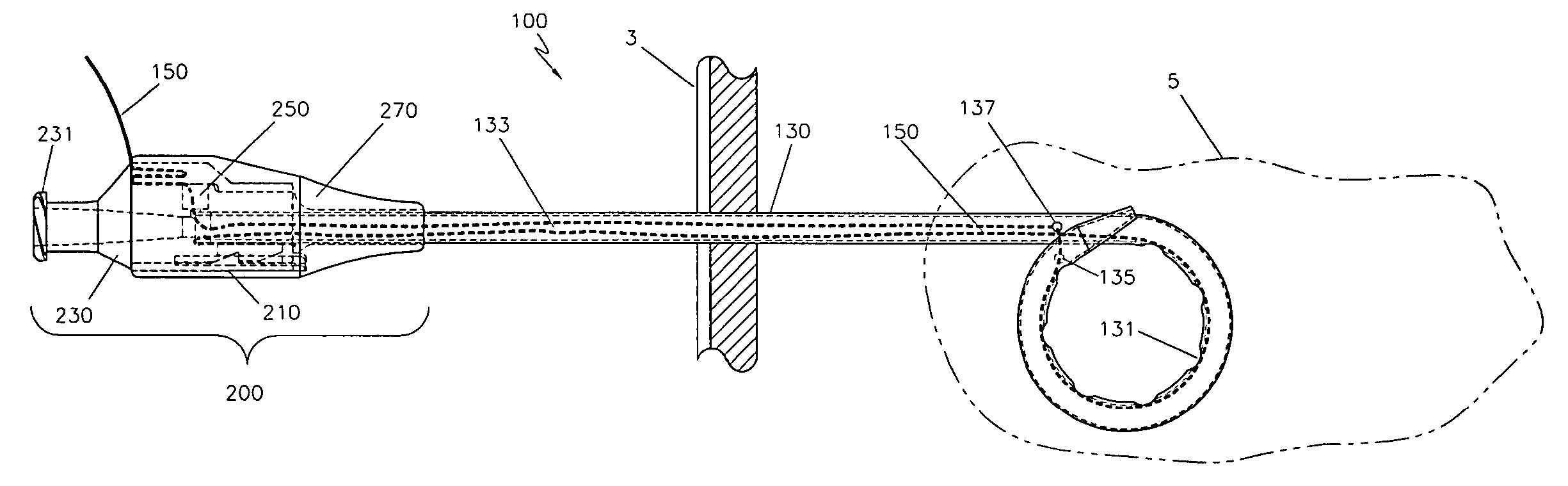
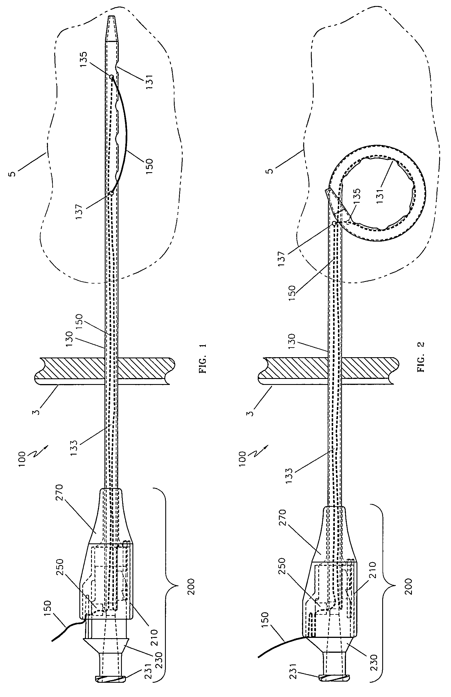
[0060] A catheter 100 consistent with the present invention is shown inserted through the body wall 3 of a patient and then into a body cavity 5. The catheter may be for the purposes of drainage of infected fluids, removal of urine, infusion of nutrition, or other uses.

[0061]FIG. 1 illustrates a catheter 100 having a locking or latching hub assembly 200 consistent with the present invention. Catheter 100 is comprised of a catheter shaft or tube 130 having a proximal and distal portion or end. The distal end typically has at least one hole 131 and another hole 137 into at least one internal lumen 133. Even though the catheter shown in the figures has only a single lumen, any number of lumens may be used with the present invention.

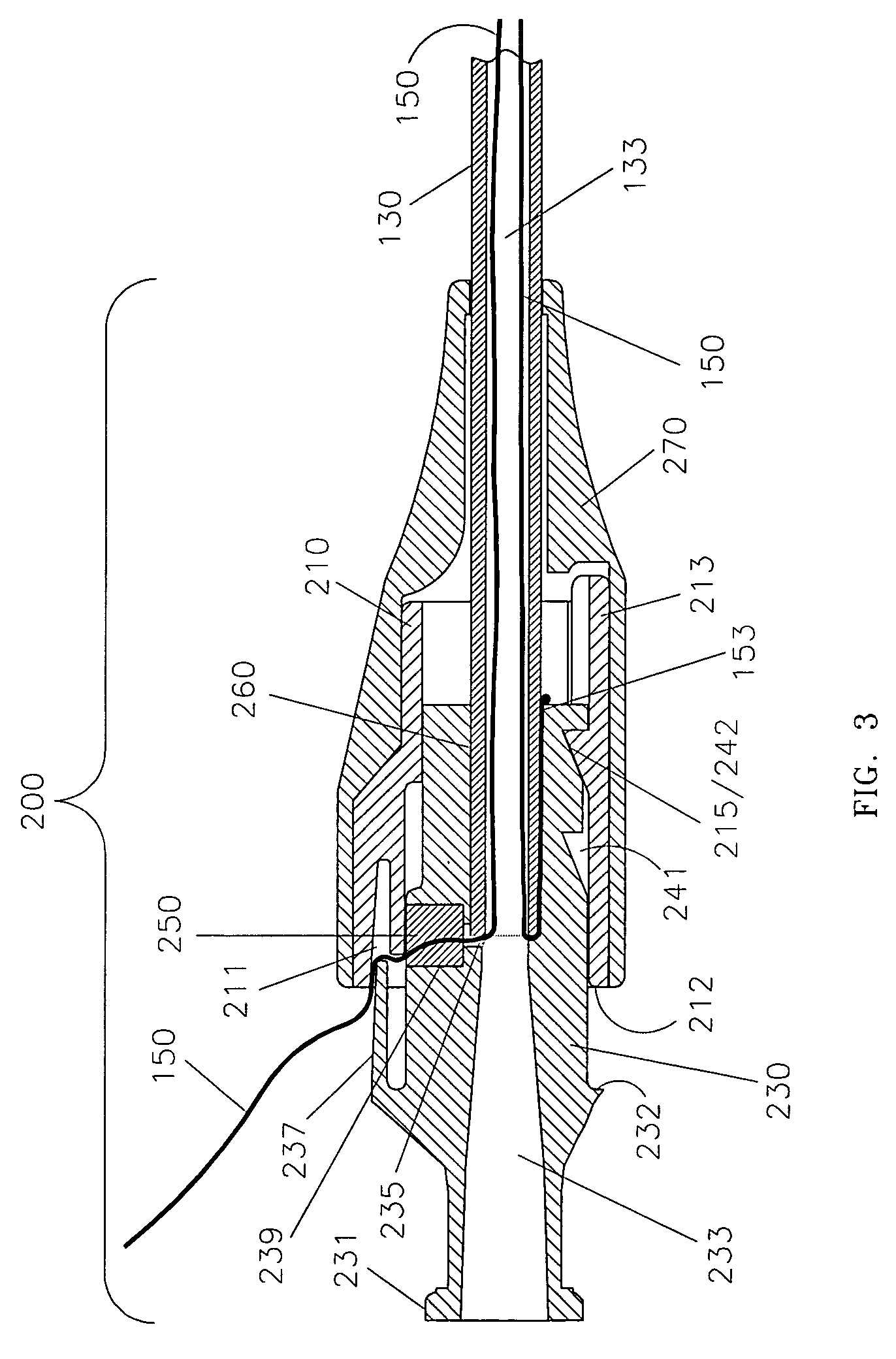
[0062] The proximal end of the catheter shaft is connected to a hub 230 of a latching hub assembly 200 at hub / shaft bond 260, shown in FIG. 3. The shaft 130 is secured to the hub at bond 260 using adhesive or other bonding techniques well known in the art....


PUM


Abstract

A catheter designed to be anchored in an internal cavity of a patient such as a drainage catheter employs a novel hub design. The hub has a slide member slidably coupled to the hub and a latch that latches the hub and the slide member together when the slide member slidably moves relative to the hub. Preferably, latching takes place when the slide member moves relative to the hub in an axial direction of the hub. A manually operable release member is provided on the hub such that the latch is disabled from unlatching unless the release member is manually operated. This feature advantageously limits a person's ability to accidentally unlatch the hub.

Description

CROSS REFERENCE TO RELATED APPLICATION [0001] This application claims priority to U.S. provisional patent application No. 60 / 520,606, filed Nov. 17, 2003, which is incorporated herein by reference.FIELD OF THE INVENTION [0002] The present invention relates to a catheter designed to be inserted into a body cavity, and more specifically, to a catheter having an anchoring end. BACKGROUND OF THE INVENTION [0003] There are several types of prior art catheters designed for insertion into a body cavity of a patient. These typically employ an anchoring device in the end of the catheter intended to reduce the risk of accidentally pulling the catheter out of the cavity. One type of such catheter employs a suture that is accessible from outside of the patient, passes through a connector on the catheter into internal opening (or lumen) of the shaft of the catheter. It then exits through the tip and reenters the lumen at a more proximal location where it can be secured inside of the lumen or on ...

Claims


Application Information

Patent Timeline
IPC IPC(8): A61M3/00A61M25/00A61M29/00A61M39/10
CPCA61M25/0097A61M25/04A61M2025/0163A61M2039/1044A61M39/1011A61B17/0483
Inventor PALMA, GIORGIO DI
Owner ANGIODYNAMICS INC
Why Eureka
Try Eureka