Self-centering end effector

a technology of end effectors and self-centering, which is applied in the direction of manufacturing tools, mechanical equipment, transportation and packaging, etc., can solve the problems of affecting the accuracy of the end effector, the accuracy of the stop, the accuracy of the drill guide and other elements of the tooling being worn or otherwise out of adjustment, and the misalignment of the elements of the manufactured produ

Inactive Publication Date: 2000-01-11
THE BOEING CO
View PDF10 Cites 25 Cited by
  • Summary
  • Abstract
  • Description
  • Claims
  • Application Information

AI Technical Summary

Problems solved by technology

However, in the real-life environment of a factory, the tooling receives some heavy and sometimes abusive use and the accuracy of the stops, drill guides, and other elements of the tooling frequently become worn or otherwise out of adjustment.
When this happens, the manufacturing processes on the part can be performed at an incorrect location

Method used


Image

  • Self-centering end effector
  • Self-centering end effector
  • Self-centering end effector

Examples


Embodiment Construction

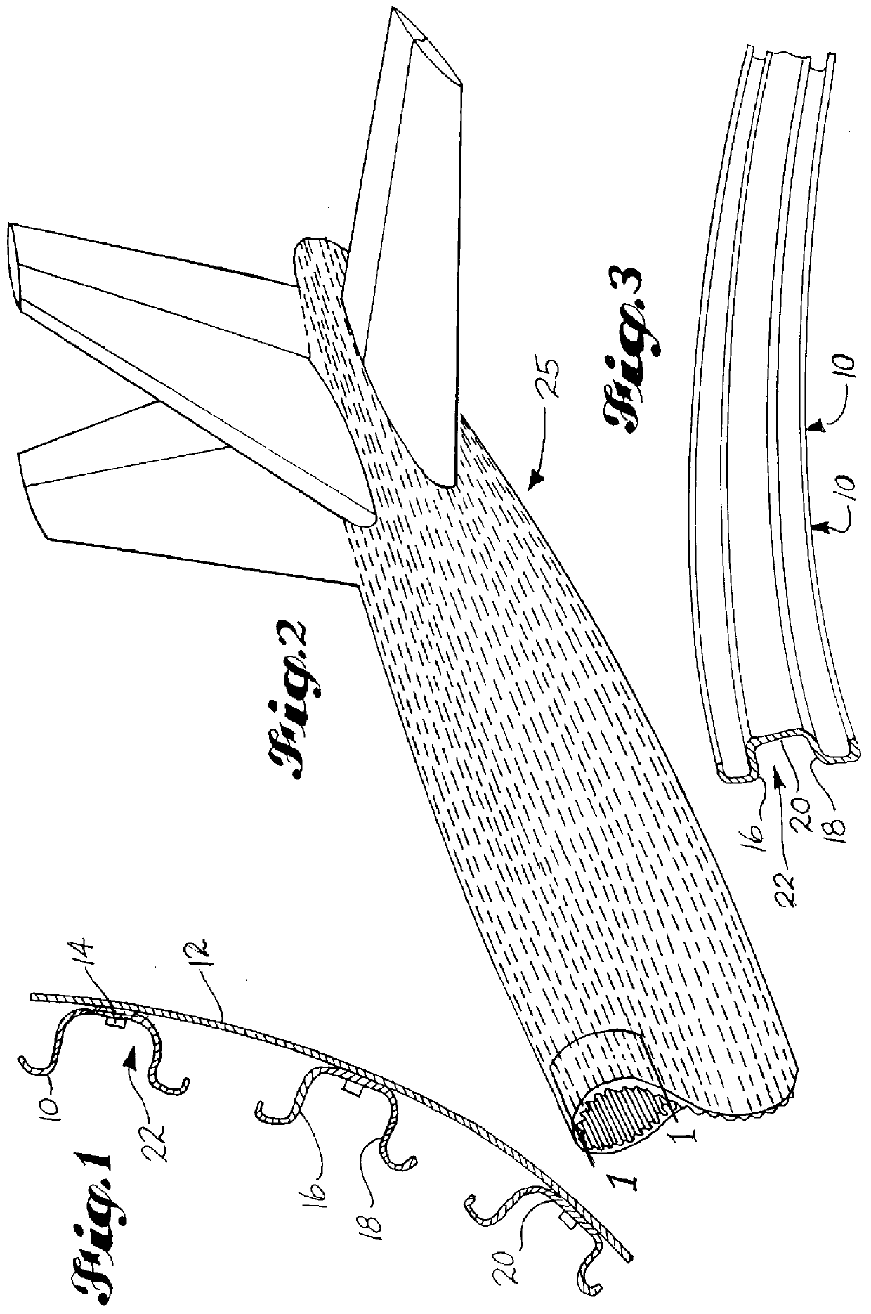
Referring now to the drawings, wherein like reference characters designate identical or corresponding parts, and more particularly to FIG. 1 showing a plurality of stringers 10 attached to a fuselage 12 of an aircraft by a plurality of fasteners 14. The stringers 10 are channel-shaped workpieces or U-shaped members, such as hat section stringers, having opposite walls 16 and 18 and a bottom 20. The opposite walls 16 and 18 along with the bottom 20 define a channel 22. FIG. 2 shows a tail section 25 of an aircraft. At the tail section 25, as well as other areas of the aircraft, the fuselage 12 narrows or otherwise makes a transition from a substantially cylindrical shape. When the shape of the fuselage 12 changes, the stringers 10 must be bent or curved to effect the change in shape. In some instances the curvature will occur along more than one axis and a compound contour will be formed, as shown in FIG. 3.

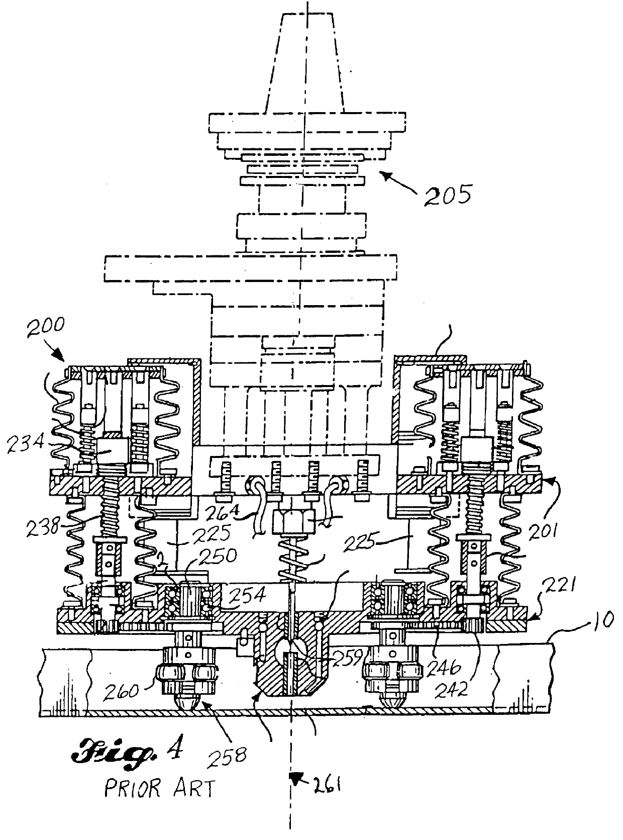
A prior art end effector 200 is shown in FIG. 4. A top plate 201 is attached ...


PUM

PropertyMeasurementUnit
Forceaaaaaaaaaa
Torqueaaaaaaaaaa

Abstract

An end effector (30) adap ttachment to and accurate positioning by a robot is provided for positioning a channel-shaped workpiece (10) at a desired position and drilling an accurately located positioning hole in the work piece, even if the workpiece is curved or has a compound contour. The end effector (30) includes a conventional speeder assembly (68) with a taper that can be grasped by the robot and rotated for transfer of torque to the speeder assembly. A flange base (54) is attached to the speeder assembly (68) and has a central opening to accommodate a drill bit (67). A housing assembly (50) is slidably mounted around the flange base (54) through a linear bearing (109). An index shaft (32) is slidably mounted partially within the housing assembly (50) through a second linear bearing (110). A collet (36) is concentrically mounted slidably about the index shaft (32). The collet (36) is adapted to expand radially when it is forced over a wider portion (34) of the index shaft (32). The radial expansion of the collet (36) provides the necessary force to position the channel-shaped workpiece (10).

Description

1. Field of the InventionThis device relates to end effectors manipulated by robots, for positioning, and more particularly to centering a channel-shaped workpiece under the end effector.2. Background InformationA need has developed in industry for an end effector that can be picked up and manipulated by a robot and used to position a workpiece and then drill a hole in the workpiece that can be used for subsequent assembly of the workpiece with other parts of a product. An end effector with this capability would be useful in many traditional manufacturing applications, but finds especially significant utility in a virtual tooling assembly, such as that which is disclosed in U.S. Pat. No. 5,560,102 to Micale et al entitled "PANEL AND FUSELAGE ASSEMBLY," that is assigned to the assignee of this invention and is incorporated herein by reference.In traditional manufacturing, parts are normally held in tooling fixtures and assembly jigs is to accurately locate the parts by butting their ...

Claims


Application Information

Patent Timeline
IPC IPC(8): B23Q3/06B23B49/00B23B49/02
CPCB23B49/02B23Q3/069B23B2215/04Y10T279/1012Y10T408/557Y10T408/03Y10T408/56245
Inventor MCCOWIN, PETER D.CORDY, DENNIS M.SMITH, RONALD J.WAGNER, DAVID L.
Owner THE BOEING CO
Why Eureka
Try Eureka