Expandable belt and tread drum

a technology of expanding belts and drums, which is applied in the field of expanding belts and tread drums, can solve the problems of limiting the range of possible diameter changes, affecting the production efficiency of drums, and limiting the possibility of achieving desired results

Inactive Publication Date: 2000-01-11
DAVIAN ENTERPRISES LLC
View PDF10 Cites 52 Cited by
  • Summary
  • Abstract
  • Description
  • Claims
  • Application Information

AI Technical Summary

Benefits of technology

In accordance with one aspect of the present invention, there is provided a belt and tread drum which includes an improved annular shell that includes a plurality of circumferentially spaced apart segments, each of which includes an arcuate surface such that the collection of segments defines an outer circumference of the drum. These segments are radially moveable inwardly and outwardly relative to the longitudinal centerline (also the rotational axis) of the drum by means of a plurality of link pairs that connect the segments to a carrier. The ...

Problems solved by technology

A substantial number of these shells have no provisions for selecting different overall diameters of the drum and therefore are limited to the manufacture of a belt and tread package for a single size tire.
Some of these existing shells have some capacity for changing the overall diameter of the drum, but are most commonly very limited in their range of possible diameter chan...

Method used


Image

  • Expandable belt and tread drum
  • Expandable belt and tread drum
  • Expandable belt and tread drum

Examples


Embodiment Construction

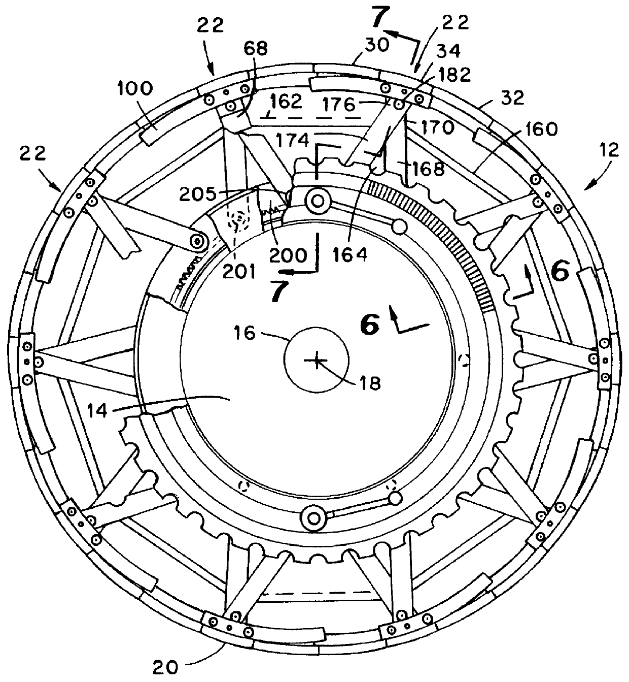
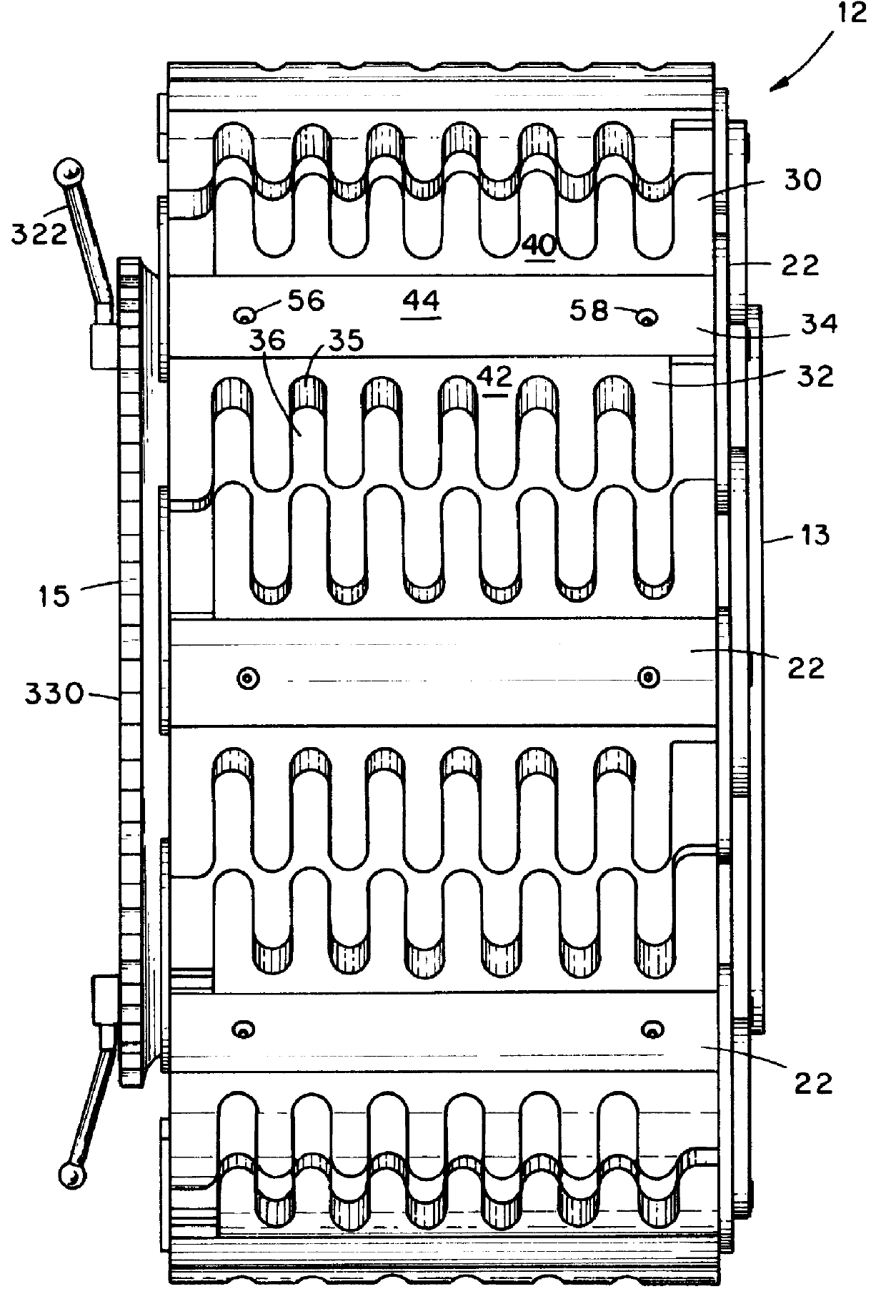
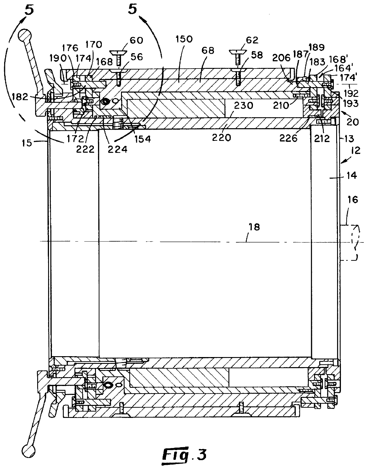
With reference to FIGS. 1 and 2, in the depicted embodiment of the present invention, there is provided a belt and tread drum indicated generally by the numeral 12 and having opposite ends 13 and 15. The depicted drum includes a cylindrical core indicated generally by the numeral 14 which is adapted to be mounted on a shaft 16 for rotation of the drum about its longitudinal axis 18 (i.e. rotational axis) by a conventional drive means (not shown). In the present invention, a generally cylindrical shell 20 is provided in circumscribing relationship to the core.

The depicted shell 20 includes a plurality of elongated segments 22, each of which is made up of a plurality of sections 30, 32 and 34. Each section includes an arcuate surface 40, 42 and 44, respectively, that is oriented facing radially outwardly of the drum. The plurality of arcuate surfaces of the segments collectively define the outer circumferential surface of the drum.

More specifically, the shell 20 of the depicted belt a...


PUM

PropertyMeasurementUnit
Diameteraaaaaaaaaa
Circumferenceaaaaaaaaaa

Abstract

A belt and tread drum having an annular shell comprising a plurality of circumferentially spaced segments, each of which is mounted on a carrier which disposed in circumscribing relationship to a generally cylindrical actuator rotatably connected with a reciprocating piston disposed within a cavity defined between the actuator and a hub fixed to a central core of the drum. Translational movement of the piston between extended and retracted positions in a direction parallel to the rotational axis of the drum is converted into selected rotational movement of the actuator relative to the hub. A plurality of sets of links interposed between the segments and the actuator and hub have their first ends commonly pivotally pinned to a segment. The second end of one link of each set of links is pivotally pinned to the actuator and the second end of the other link of each set of links is pivotally pinned to the hub. Rotation of the actuator relative to the hub controls the arcuate separation of these second ends such that bringing these second ends toward contiguity moves the segments radially outwardly, and conversely, moving these second ends arcuately apart serves to move the segments radially inwardly of the drum. A hand wheel establishes maximum and minimum rotational movement of the actuator and provides a visual indication of the radial positions of the several segments, i.e. the diameter of the drum.

Description

This invention relates to equipment for use in the manufacture of vehicle tires and particularly to a belt and tread drum having novel diameter expansion / retraction capabilities.BACKGROUND OF INVENTIONVehicle tire manufacture most commonly takes place in stages. In an early stage of the manufacturing procedure, there is formed a belt and tread package. This package comprises a plurality of strips (belts) of elastomeric material and / or other similar components that are formed into a toriodal shape by winding the strips about the outer circumference of a rotating belt and tread drum, with bonding of the strips into the belt and tread package. Commonly, the belt and tread package also has included therein metal bead rings that ultimately aid in defining the rim diameter and circumference of the tire. The package thus formed is nonexpandable in diameter. After the package has been formed on the belt and tread drum, the drum most commonly is collapsed in outer circumference to allow remo...

Claims


Application Information

Patent Timeline
IPC IPC(8): B29D30/24B29D30/20
CPCB29D30/242
Inventor BYERLEY, MARK S.
Owner DAVIAN ENTERPRISES LLC
Why Eureka
Try Eureka