Shaft selection aiding apparatus for selecting optimum shaft for a golfer

a technology for golfers and shafts, applied in golf clubs, golfing accessories, instruments, etc., can solve problems such as complaints that the shafts are too stiff or too flexible, and the complaints do not agree with head speed standards

Inactive Publication Date: 2000-01-18
MIZUNO CORPORATION
View PDF13 Cites 26 Cited by
  • Summary
  • Abstract
  • Description
  • Claims
  • Application Information

AI Technical Summary

Problems solved by technology

In recent years, as more people enjoy playing golf, some people complain about their shafts being too stiff or being too flexible.
Such complaints do not agree with the head speed standards.
Manufactures have changed their standards into a variety of forms from time to time accordingly, but all such new standards are still base

Method used


Image

  • Shaft selection aiding apparatus for selecting optimum shaft for a golfer
  • Shaft selection aiding apparatus for selecting optimum shaft for a golfer
  • Shaft selection aiding apparatus for selecting optimum shaft for a golfer

Examples


Embodiment Construction

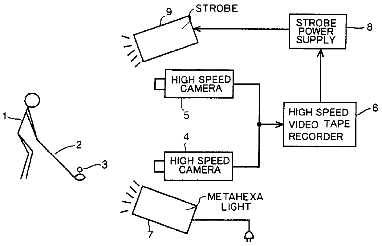
FIG. 1 is a block diagram schematically showing an image-taking / recording system for image-taking / recording the movement of a club head in one embodiment of the invention. In FIG. 1, a high speed camera is placed in order to take the image of a part of a ball 3 from the front when a golfer 1 swings a club 2 and hits the ball. A high speed camera 5 is placed in order to take the image of the top of the head of golfer 1 from the front. These high speed cameras 4 and 5 whose number of frames is 1 / 200 sec take the images at a time. Video outputs from high speed cameras 4 and 5 are recorded by a high speed video tape recorder 6. A metahexa light 7 is provided to illuminate golfer 1 and ball 3. Further, in order to strobe-illuminate golfer 1 a strobe light 9 is provided, which is activated by a strobe power supply 8 and emits light in response to pressing of the recording button of high speed video tape recorder 6 before golf 1 starts swinging golf club 2.

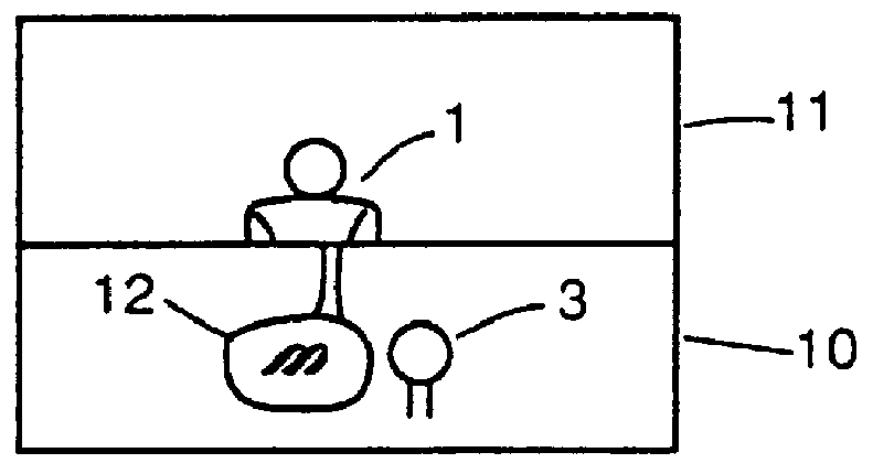
FIG. 2 is a block diagram schemat...


PUM


Abstract

A high speed camera takes an image in the vicinity of a ball 3 and a club head 12, while a high speed camera 5 takes an image in the vicinity of the top of the swing of a golfer 1, and the images are recorded in a high speed video tape recorder 6. The recorded images are reproduced, swing time, a swing speed and a head speed are detected using a personal computer 15, and a shaft with an optimum flex for the golfer is selected based on the swing time, the swing speed, the swing time and the head speed, or the swing speed and the head speed.

Description

The present invention relates generally to an apparatus for selecting a shaft with an optimum flex for a golfer, and more particularly, to an apparatus for selecting an optimum flex for a golfer by which the golfer can select a shaft with a flex the most suitable for him / her.DESCRIPTION OF THE BACKGROUND ARTGolf clubs having a variety of shaft flexes are available, and a golfer must select a golf club with a flex the most suitable for him / her. Conventionally, an optimum flex for a golfer used to be determined based only on a head speed produced from time required for a club head to move over a fixed distance till impact.In recent years, as more people enjoy playing golf, some people complain about their shafts being too stiff or being too flexible. Such complaints do not agree with the head speed standards. Manufactures have changed their standards into a variety of forms from time to time accordingly, but all such new standards are still based on head speed standards, and other mea...

Claims


Application Information

Patent Timeline
IPC IPC(8): A63B59/00A63B69/36A63B53/00A63B24/00A63B69/00A63B102/32
CPCA63B24/0003A63B24/0021A63B59/0074A63B69/3611A63B71/0622A63B53/00A63B2024/0028A63B2024/0031A63B2207/02A63B2220/05A63B2220/40A63B2220/51A63B2220/54A63B2220/805A63B2220/806A63B2220/807A63B2220/808A63B2220/833A63B60/42A63B69/36A63B2225/74A63B60/46A63B69/3605
Inventor NARUO, TAKESHISAITO, TAKESHINOGUCHI, SHUICHI
Owner MIZUNO CORPORATION
Why Eureka
Try Eureka