Continuously variable reciprocating transmission device

a transmission device and continuously variable technology, applied in the direction of gearing, pivots, shafts and bearings, etc., can solve the problems of the prior art transmission device with continuously variable gear ratios, and achieve the effect of simple design and operation

Inactive Publication Date: 2000-01-25
PARK BRET J
View PDF18 Cites 11 Cited by
  • Summary
  • Abstract
  • Description
  • Claims
  • Application Information

AI Technical Summary

Benefits of technology

It is therefore an object of the present invention to provide a variable-ratio transmission which is simple is design and operation.

Problems solved by technology

However, there have been many practical difficulties with the prior art transmission devices which offer continuously variable gear ratios.

Method used


Image

  • Continuously variable reciprocating transmission device
  • Continuously variable reciprocating transmission device
  • Continuously variable reciprocating transmission device

Examples


Embodiment Construction

For the purposes of promoting an understanding of the principles in accordance with the invention, reference will now be made to the embodiments illustrated in the drawings and specific language will be used to describe the same. It will nevertheless be understood that no limitation of the scope of the invention is thereby intended. Any alterations and further modifications of the illustrated apparatus, and any additional applications of the principles of the invention as illustrated herein, which would normally occur to one skilled in the relevant art and possessed of this disclosure, are to be considered within the scope of the invention claimed.

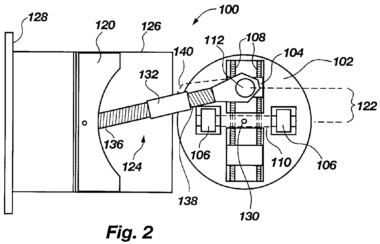
Applicant has discovered a new design for a variable-ratio transmission device capable of transmitting force while varying gear ratios during movement of the gears. In FIG. 1 is shown a transmission device, designated generally at 10. The transmission 10 includes a first rotational member 12, configured for attachment to a means 14, which ...


PUM


Abstract

A variable-ratio transmission device. A first translational member is pivotally intercoupled to a first rotational member by at least one connecting arm. The connecting arm has a first portion pivotally connected to the first translational member at a first pivot point, and a second portion pivotally and adjustably connected to the first rotational member at a first radial attachment point removed from the center of rotation of the first rotational member. The first radial attachment point and the center of rotation thereby define a first attachment radius. The location of the first radial attachment point with respect to the first rotational member is variable to thereby increase and decrease the first attachment radius, which in turn modifies a ratio of movement between the first rotational member and the first translational member.

Description

1. The Field of the InventionThe present invention relates generally to vehicle transmissions. More particularly, it concerns a variable-ratio transmission device.2. The Background ArtTransmission devices are well known in the field of motorized vehicles for converting and transmitting the force generated by an engine to an output shaft. It is known to make efficient use of the motor power by adjusting the gear ratio between the input and output shafts responsive to variation in loads on the output shaft, or on the input shaft. For example, a higher gear ratio often provides a more efficient transfer of force for larger loads on the output shaft. Conversely, a lower gear ratio often suffices for lesser loads on the output shaft.The need to optimize the motor power by varying the gear ratio has motivated the development of many different transmission devices capable of shifting between gear ratios. The standard transmission is known in the field to permit an operator to shift between...

Claims


Application Information

Patent Timeline
Patent Type & Authority Patents(United States)
IPC IPC(8): F16L3/02F16L3/04
CPCF16L3/04Y10T74/18296Y10T74/2179Y10T74/218Y10T74/1675F16H29/00
Inventor PARK, BRET J.
Owner PARK BRET J
Why Eureka
Try Eureka