Method for lining a tubular conduit

a tubular conduit and pipe body technology, applied in the field of tubular conduit lining, can solve the problems of virtually impossible to set up a bypass passage for the drain water, difficult to practice the technique of draining water to bypass the repair portion of the pipe,

Inactive Publication Date: 2000-02-15
SHONAN GOSEI JUSHI SEISAKUSHO KK +3
View PDF17 Cites 34 Cited by
  • Summary
  • Abstract
  • Description
  • Claims
  • Application Information

AI Technical Summary

Problems solved by technology

However, the above-stated method of diverting the drain water to bypass the repair portion of the pipe is not always easy to practice; for example, if a road, a railway, or a river lies across the line connecting two manholes between which the pipe to be repaired extends, it is virtually impossible to set up a bypass passage for the drain water.

Method used


Image

  • Method for lining a tubular conduit
  • Method for lining a tubular conduit
  • Method for lining a tubular conduit

Examples


Embodiment Construction

Next, an embodiment of the invention will be described with reference to the attached drawings.

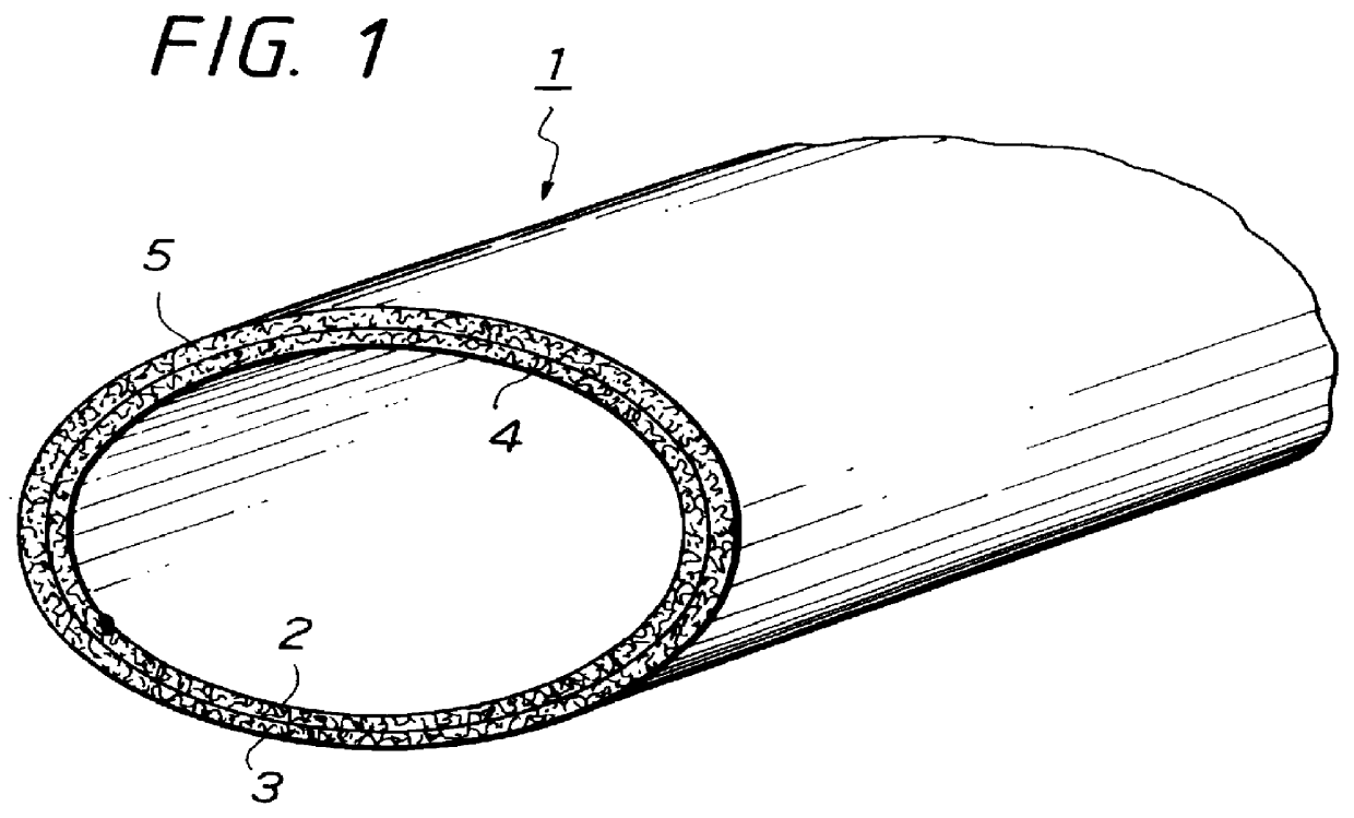
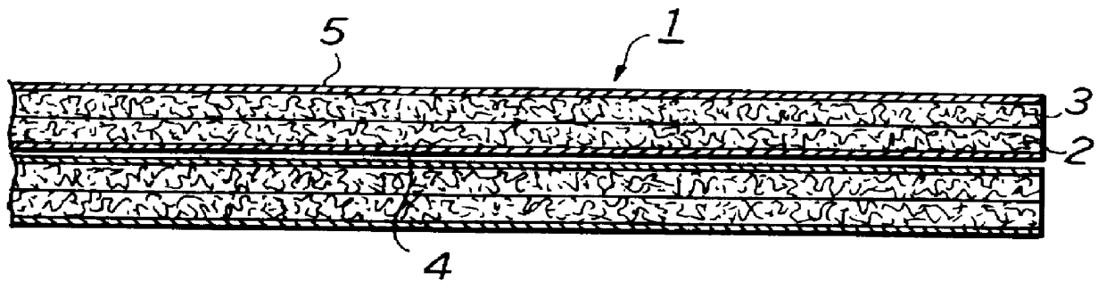
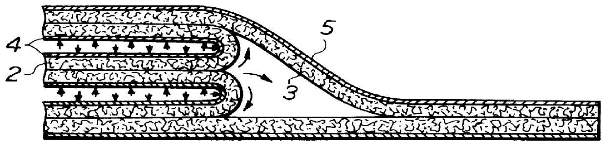
FIG. 1 is a perspective view of part of a tubular liner used in a pipe lining method according to the invention, and FIGS. 2 and 3 are sectional views to illustrate steps in a procedure for making the tubular liner used in the pipe lining method.

As shown in FIG. 1, a tubular liner 1 used in the pipe lining method of the invention comprises a long laminated tube of an inner resin-absorbent fabric layer 2 and an outer resin-absorbent fabric layer 3, and both the inner and outer faces of the two-layered tubular liner 1 are covered with a layer of highly-airtight plastic film 4, 5, respectively. The resin-absorbent fabric layers 2, 3 are to be soaked with a liquid thermosetting resin.

Incidentally, the resin-absorbent fabric to form the layers 2, 3 is a nonwoven fabric obtained by bonding or punch-pressing a mass of fiber such as of polyester, nylon, and polypropylene, and the plastic film 4, 5...


PUM

PropertyMeasurementUnit
diameteraaaaaaaaaa
angleaaaaaaaaaa
thicknessaaaaaaaaaa

Abstract

A method for lining an underground sewer pipe: (a) preparing a tubular liner made of a tubular fabric layer soaked with a thermosetting liquid resin and two layers of airtight film with which inner and outer walls of the fabric layer are covered; (b) inserting the liner assembly into the tubular conduit from the front end by pulling the front end with a rope; (c) inflating the tubular liner assembly after closing the front and the rear ends thereof; (d) heating the thermosetting resin to thereby harden the fabric layer of the liner assembly; and (e) removing those portions of the tubular liner assembly which do not partake in lining the tubular conduit.

Description

1. Field of the InventionThe present invention relates to a method for lining a tubular conduit with a tubular liner, which is composed of a tube of a nonwoven fabric impregnated with a thermosetting liquid resin and laminated both inner and outer faces with a highly airtight film.2. Description of the Prior ArtWhen a tubular conduit, such as underground pipelines and passageways, becomes defective or too old to perform properly, the tubular conduit is repaired and rehabilitated without digging the earth to expose it and disassembling it into sections. This non-digging method of repairing an underground tubular conduit has been known and practiced commonly in the field of civil engineering. Typically, the method is disclosed by Japanese Provisional Patent Publication (Kokai) No. 60-242038.According to this publication, this tubular conduit repair method comprises inserting a sufficiently long tubular flexible liner bag into the tubular conduit to be repaired by means of a pressurize...

Claims


Application Information

Patent Timeline
Patent Type & Authority Patents(United States)
IPC IPC(8): B29C63/34F16L55/165F16L55/162F16L58/10B29K101/10B29K105/08B29L23/00F16L1/00F16L55/16
CPCB29C63/34F16L55/1654
Inventor KAMIYAMA, TAKAOYOKOSHIMA, YASUHIROENDOH, SHIGERUAOKI, HIROYUKI
Owner SHONAN GOSEI JUSHI SEISAKUSHO KK
Why Eureka
Try Eureka