Drum assembly for a wood chipper

a drum and wood chipper technology, applied in the direction of peelers, solid separation, flat surfacing machines, etc., can solve the problems of limited wood fed into the wood chipper, and the typical use of fans in the chipper

Inactive Publication Date: 2000-03-07
BANDIT IND
View PDF55 Cites 50 Cited by
  • Summary
  • Abstract
  • Description
  • Claims
  • Application Information

AI Technical Summary

Problems solved by technology

Although this type of wood chipper has worked well, it suffers from the disadvantage that the size of wood fed into the wood chipper is limite...

Method used


Image

  • Drum assembly for a wood chipper
  • Drum assembly for a wood chipper
  • Drum assembly for a wood chipper

Examples


Embodiment Construction

)

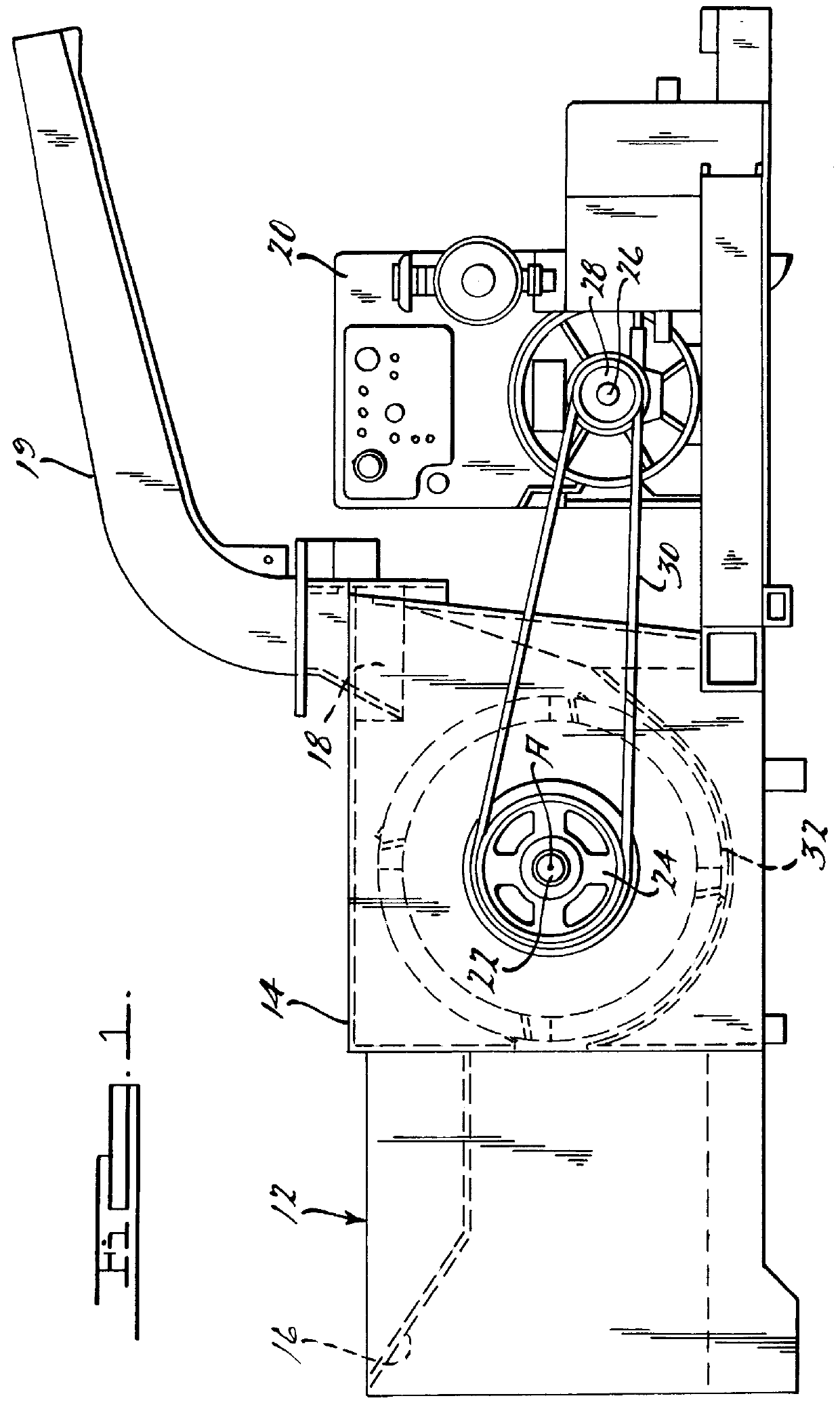
Referring now to the drawings and in particular FIGS. 1 and 2, one embodiment of a drum assembly 10, according to the present invention, is shown for a wood chipper, generally indicated at 12. The wood chipper 12 includes a housing 14 having an inlet 16 and an outlet 18. The wood chipper 12 also includes a chute 19 connected to the outlet 18 of the housing 14 to expel wood chips past a rear end of the wood chipper 10. The wood chipper 12 further includes the drum assembly 10 disposed within the housing 14 between the inlet 16 and outlet 18 for rotation about a horizontal axis A. The wood chipper 12 also includes an engine 20 mounted in conjunction with the housing 14 and coupled to the drum assembly 10 by suitable means to cause rotation of the drum assembly 10 about its axis A. It should be appreciated that the housing 14 and engine 20 are basically conventional and known in the art.

The wood chipper 12 includes a rotatable shaft 22 and a pulley 24 disposed about one end of the sha...


PUM


Abstract

A drum assembly for a wood chipper includes a drum rotatable about a horizontal axis and a plurality of pockets disposed circumferentially about the drum. The drum assembly also includes a plurality of blades operatively connected to the drum, one of the blades partially overlapping one of the pockets. Each of the pockets has a depth greater than a width thereof and a capacity to hold a wood volume of a maximum size of wood being chipped.

Description

1. Field of the InventionThe present invention relates generally to wood chippers and, more specifically, to a drum assembly for a wood chipper.2. Description of the Related ArtIt is known to provide a wood chipper for chipping wood such as brush, branches and the like to produce wood chips. One type of wood chipper known in the art includes a rotatable drum having a knife or blade for chipping the wood entering the wood chipper and reducing it to wood chips. Typically, the drum has a single knife or multiple knives extending axially across the drum.Although this type of wood chipper has worked well, it suffers from the disadvantage that the size of wood fed into the wood chipper is limited. Another disadvantage of the wood chipper is that the wood chipper typically uses fans to help directly eject the wood chips from the wood chipper.Accordingly, the present invention is a drum assembly for a wood chipper including a drum rotatable about a horizontal axis and a plurality of pockets...

Claims


Application Information

Patent Timeline
IPC IPC(8): B27L11/02B27L11/00
CPCB27L11/002B27L11/02
Inventor MOREY, MICHAEL BOYDPETERMAN, MICHAEL JOHNBLOOMQUIST, BRIAN LEE
Owner BANDIT IND
Why Eureka
Try Eureka