Painting tool

a paint tool and auxiliary roller technology, applied in the field of paint tools, can solve the problems of high expected cost, cumbersome use, and difficulty in maintaining, and achieve the effect of reducing the number of components of the paint tool

Inactive Publication Date: 2000-03-14
ER POH LEONG
View PDF9 Cites 13 Cited by
  • Summary
  • Abstract
  • Description
  • Claims
  • Application Information

AI Technical Summary

Benefits of technology

It is an object of the present invention to reduce the number of components in paint tool without compromising the convenience and maintenance of prior art paint roller.

Problems solved by technology

The absence of these prior art paint tools from the market may be attributed to the fact that these alternatives are expensive, difficulty to maintain, and cumbersome to use.
The higher expected cost is related to the large number of auxiliary rollers besides the main roller.
It follows that the user will find these prior art paint rollers less maneuverable than the regular paint roller.

Method used


Image

  • Painting tool
  • Painting tool
  • Painting tool

Examples


Embodiment Construction

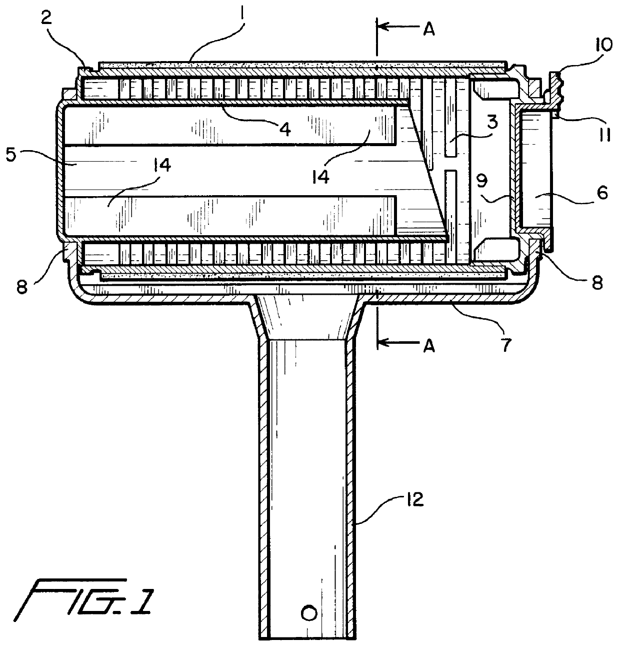
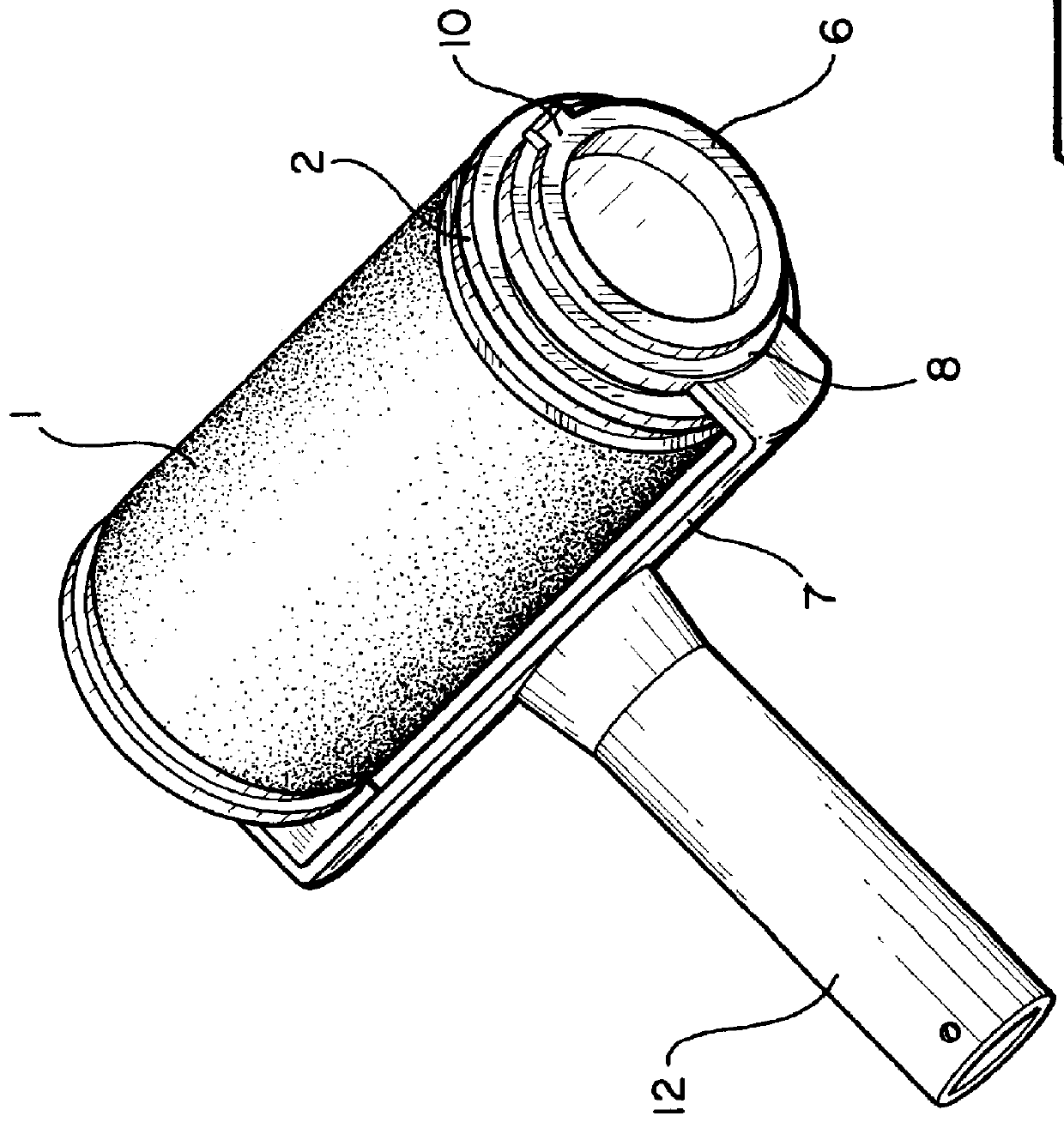
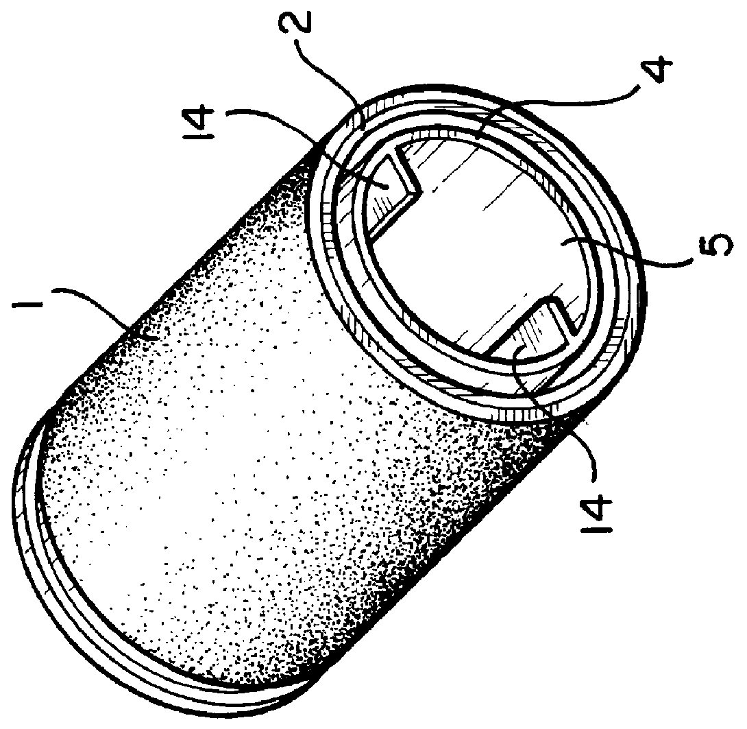
FIG. 1 is a front, cross sectional, elevational view of the present invention together with handle frame. The present invention comprises an applicator 1 laid over the external surface of a roller 2 which is rotatably mounted at two ends walls 8 of a handle frame 7. The applicator is preferably made of absorbent material such as foam or sponge material. The interior of the roller 2 communicates with the external surface of the roller via a plurality of slits 3 on the roller. Disposed within the interior and preferably concentrically with the longitudinal axis (not shown) of the roller 2 is a reservoir 5 for receiving and storing paint through an opening 9. The reservoir 5 has an open ended wall 4 for retaining residue paint, and more importantly, preventing paint from flowing out of the roller when the roller is rested in a substantially vertical position. Although the wall 4 is shown to have a cylindrical shape in the figures, it can take on other shapes. Extended from the interior...


PUM


Abstract

PCT No. PCT/SG97/00004 Sec. 371 Date Jun. 17, 1998 Sec. 102(e) Date Jun. 17, 1998 PCT Filed Feb. 4, 1997 PCT Pub. No. WO97/28904 PCT Pub. Date Aug. 14, 1997A paint roller with an internal reservoir for receiving and dispensing paint. The interior of the cylindrical roller communicates with the external surface via a plurality of slits running substantially normal to the longitudinal axis of the shell. An applicator is laid over the external surface of the shell. Paint of the internal reservoir is dispensed evenly and automatically over the slits.

Description

The present invention relates to apparatus for applying fluids over surfaces. In particular, the present invention is a tool for storing and applying paint.Paint brush and paint roller are well known tool for applying paint over surfaces of building and walls. For painting large surfaces, paint roller and pan remain the instruments of choice for painting professionals and do-it-yourself individuals because they are inexpensive and apply paint consistently. However, the need to replenish the roller frequently attracts a number of new proposals and invention.In general, the prior art teaches the combination of internal paint reservoirs and either a single or plurality of rollers. See, for example, U.S. Pat. Nos. 3,905,295; 4,167,349; and the list of patents disclosed in U.S. Pat. No. 4,555,195. These prior art painting tools having internal paint reservoirs and roller(s) have a common feature: paint from the reservoirs is applied over the external surface of the roller before the pain...

Claims


Application Information

Patent Timeline
Patent Type & Authority Patents(United States)
IPC IPC(8): B05C17/02B05C17/025
CPCB05C17/025
Inventor ER, POH LEONG
Owner ER POH LEONG
Why Eureka
Try Eureka