Liquid crystal apparatus

a technology of liquid crystal apparatus and liquid crystal, which is applied in the field of liquid crystal apparatus, can solve the problems of remarkably degraded display quality, awkward image called "tailing" and "tailing" on the display

Inactive Publication Date: 2000-04-04
CANON KK
View PDF34 Cites 21 Cited by
  • Summary
  • Abstract
  • Description
  • Claims
  • Application Information

AI Technical Summary

Benefits of technology

Another object of the present invention is to provide driving apparatus for a display panel having solved a problem of flickering on a display.

Problems solved by technology

However, a ferroelectric liquid crystal device as mentioned above involves a problem that it causes flickering when subjected to multiplexing drive.
In the case of an ordinary frame frequency of 30 Hz, the above half-selected voltage is applied at a half frame frequency of 15 Hz, so that the flickering is noticeable to an observer and results in a remarkably degraded display quality.
Another problem of such a multiplexing drive method wherein one picture is formed-through a plurality of writing frame scans is occurrence of an awkward image called "tailing" on the display picture, which is observable when the drive method is applied to a motion picture display as in a television display or letter-scrolling on a screen of a word processor.
It has been found that these unnecessary black display states cause "tailing" on a display at the time of scrolling.
First is that the response speed is quite fast.

Method used


Image

  • Liquid crystal apparatus
  • Liquid crystal apparatus
  • Liquid crystal apparatus

Examples


example 2

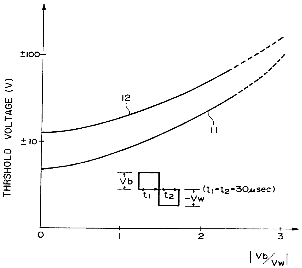
A ferroelectric liquid crystal cell was prepared in the same manner as in Example 1 except that the "CS-1014" (trade name) was changed to another ferroelectric liquid crystal "CS-1011" (trade name, available from Chisso K.K.). The thus obtained ferroelectric liquid crystal cell was supplied with an alternating pulse with various amplitudes Vb and Vw as shown in FIG. 1. The inversion voltages (Vw) thus measured were plotted to provide the characteristic curve 12 shown in FIG. 1.

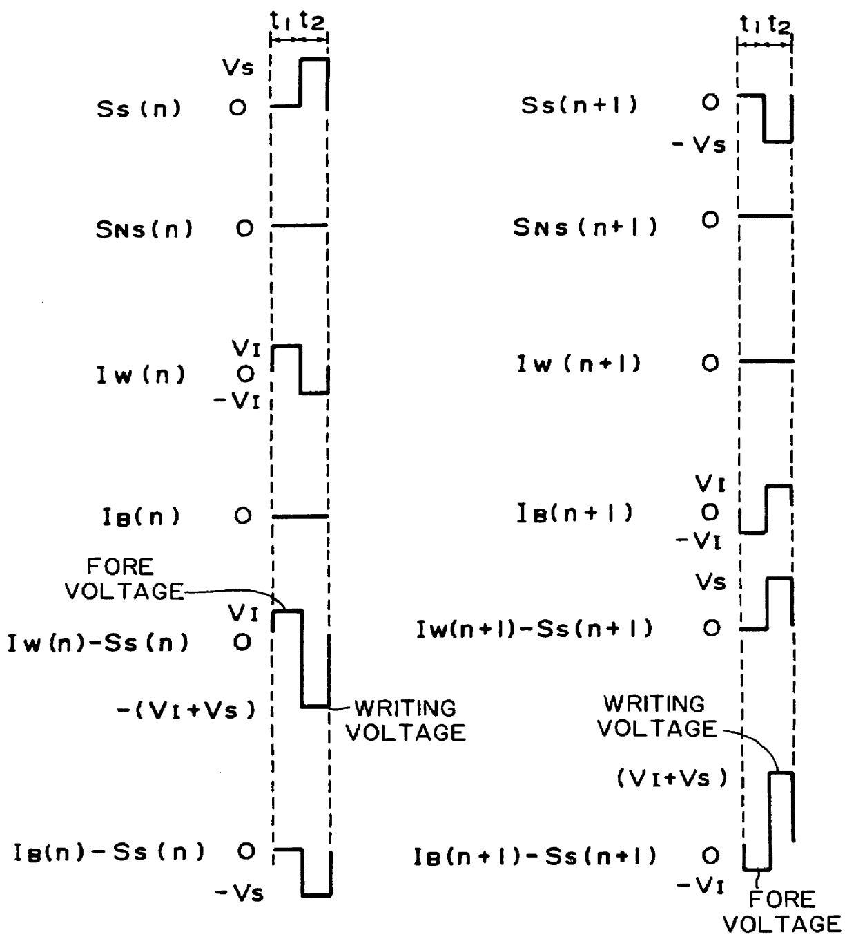
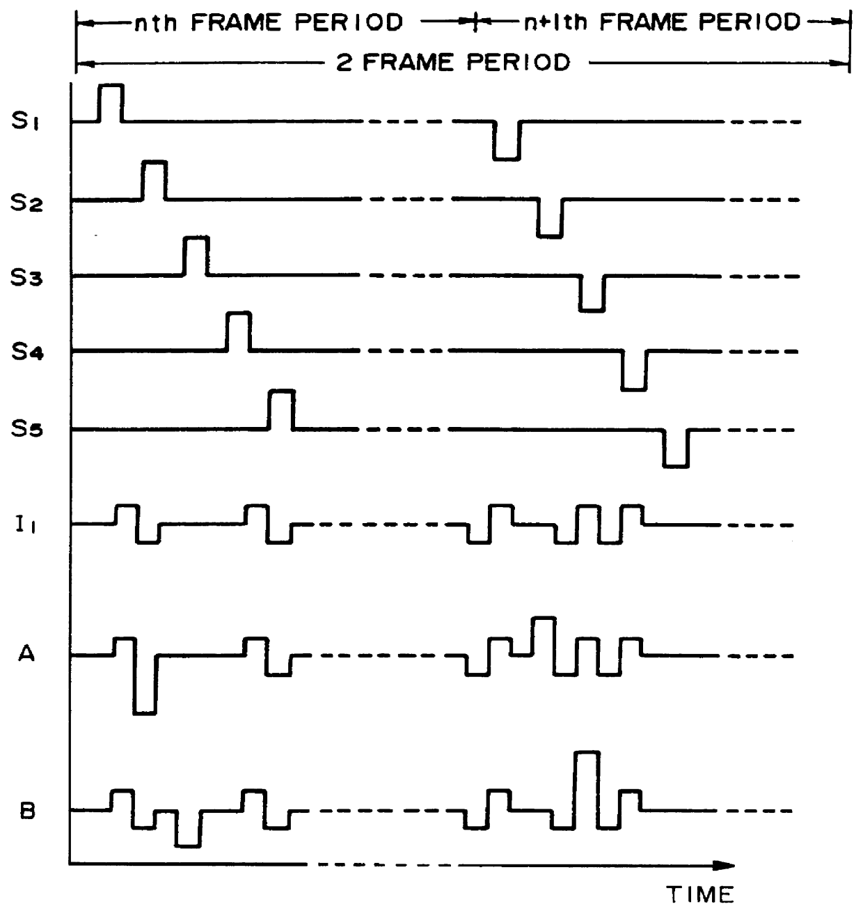
Then, multiplexing drive was effected by applying driving voltage waveforms shown in FIG. 6 to the above ferroelectric liquid crystal cell. By setting the voltage .vertline.V.sub.I +V.sub.S .vertline. to 21 volts, the ratio .vertline.V.sub.I .vertline. / .vertline.V.sub.S +V.sub.I .vertline.to 1 / 3, and each of the phases t.sub.1, t.sub.2 and t.sub.3 to 30 .mu.sec, a normal static picture was formed.

On the other hand, when it was tried to form a static picture in the same manner as above except that the ratio .ve...


PUM


Abstract

A liquid crystal apparatus comprises scanning electrodes and data electrodes intersecting with each other to form a pixel at each intersection, and a ferroelectric liquid crystal disposed between the scanning electrodes and data electrodes. The apparatus includes a first unit for applying to the scanning electrodes at least two scanning selection signals in at least two vertical scanning periods; the scanning selection signals having mutually different waveforms and each having a pulse of one or the other voltage polarity with respect to the level of a voltage applied a scanning electrode when it is not selected; and a second unit for applying data pulses to the data electrodes in phase with said pulse of one or the other voltage polarity. The first unit and second unit in combination apply a fore voltage pulse to a pixel on a scanning electrode selected by application of the pulse of one or the other voltage polarity prior to each application of a writing voltage formed by combination of the pulse of one or the other polarity and an information pulse. The fore voltage pulse has a polarity opposite to that of the writing voltage and an amplitude which is +E,fra 1 / 2+EE or less of that of the writing voltage.

Description

FIELD OF THE INVENTION AND RELATED ARTThe present invention relates to a liquid crystal apparatus using a ferroelectric liquid crystal capable of providing a discriminable contrast depending on the direction of an electric field applied thereto.The use of a liquid crystal device showing bistability has been proposed by Clark and Lagerwall in U.S. Pat. No. 4,367,924; Japanese Patent Application (Kokai) 56-107216. As the bistable liquid crystal, a ferroelectric liquid crystal showing chiral smectic C phase (SmC*) or H phase (SmH*) is generally used. The ferroelectric liquid crystal assumes either a first optically stable state or a second optically stable state in response to an electric field applied thereto and retains the resultant state in the absence of an electric field, this showing a stability. Further, the ferroelectric liquid crystal quickly responds to a charge in electric field, and thus the ferroelectric liquid crystal device is expected to be widely used in the field of ...

Claims


Application Information

Patent Timeline
Patent Type & Authority Patents(United States)
IPC IPC(8): G09G3/36
CPCG09G3/3629G09G2310/0224G09G2310/06G09G2320/0247G09G2310/065G09G2320/0209G09G2310/061
Inventor TANIGUCHI, OSAMUINOUE, HIROSHIMIZUTOME, ATSUSHIMIHARA, TADASHIONITSUKA, YOSHIHIROTERADA, MASAHIRO
Owner CANON KK
Why Eureka
Try Eureka