Power converter with improved control of its main switches, and application to a power converter having three or more voltage levels

a technology of power converters and main switches, applied in the direction of electric variable regulation, process and machine control, instruments, etc., can solve the problems of converters not always operating at maximum load, excessive efficiency loss, and economic inacceptability

Inactive Publication Date: 2000-04-04
POWER SUPPLY SYST HLDG THE NETHERLANDS
View PDF8 Cites 60 Cited by
  • Summary
  • Abstract
  • Description
  • Claims
  • Application Information

AI Technical Summary

Benefits of technology

The present invention is based on the observation that applying that conventional solution leads to maximum losses being accepted by way of safety precaution, even though that is generally excessive.

Problems solved by technology

That is not economically acceptable.
In addition, the converter does not always operate at maximum load; this is true in particular when operating with AC, but it can also happen in most DC applications.
Again the threshold is set so as to comply with the most unfavorable operating conditions which are encountered only rarely, and again complying with safety needs gives rise to excessive loss of efficiency.

Method used


Image

  • Power converter with improved control of its main switches, and application to a power converter having three or more voltage levels
  • Power converter with improved control of its main switches, and application to a power converter having three or more voltage levels
  • Power converter with improved control of its main switches, and application to a power converter having three or more voltage levels

Examples


Embodiment Construction

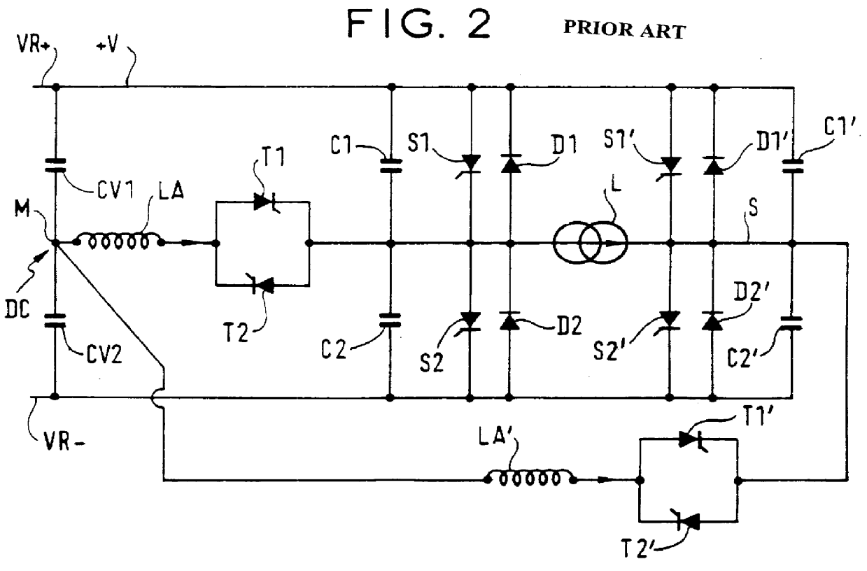
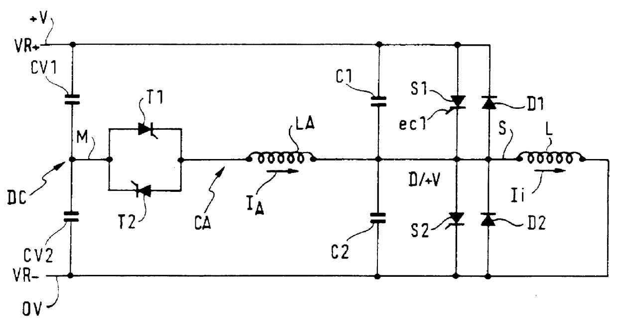
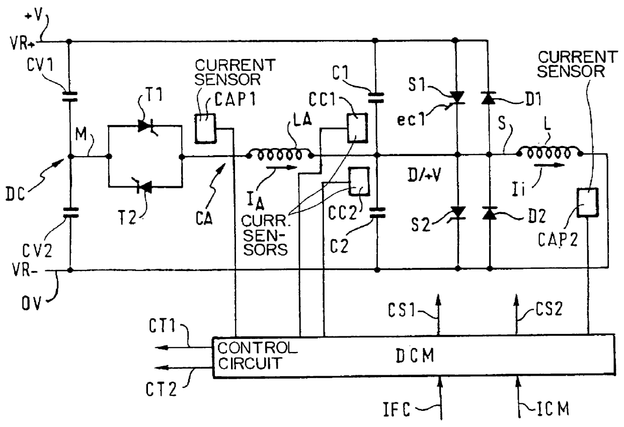
The embodiment of the invention shown in FIG. 3 is intended for controlling the operation of the arm of the converter shown in FIG. 1, or of one of the arms of the converter shown in FIG. 2. Thus, the circuit of FIG. 3 comprises current sensors for substantially continuously evaluating the current flowing through the conductors with which they are respectively associated, comprising in particular a first sensor CAPl associated with auxiliary circuit CA, and evaluating more particularly the current flowing through the auxiliary inductor LA, and a second sensor CAP2 doing the same for the current flowing through the load, and / or a third sensor CC1 and a fourth sensor CC2 for evaluating respectively the currents flowing through each of the snubber capacitors C1 and C2. The sensors are connected to an operation control device DCM which also receives operation control instructions via an input ICM together with other information concerning the operation of the converter via an input IFC....


PUM


Abstract

A power converter having two main switches connecting an outlet either to a positive rail or to a negative rail, two free-wheel diodes enabling the current through the load to be maintained, two snubber capacitors, and an auxiliary circuit. The auxiliary circuit includes an auxiliary inductor in series with two auxiliary switches coupled between the outlet and a midpoint of a capacitive voltage divider that provides a midpoint voltage. A detector detects current oscillation between the auxiliary inductor and the snubber capacitors, and then switches off the oscillation current and allows the intended main switch to conduct in response to the interruption.

Description

The present invention relates to so-called "soft switching" power converters, in particular the power converters described in the article entitled "High power transistor inverters--potential for single device operation at 1000 A and 800 V", by G. A. Fisher, published in the minutes of the "16th Universities Power Engineering Conference", Sheffield, Great Britain, in the article entitled "Resonant snubbers with auxiliary switches", by W. McMurray, published in IEEE Transactions on Industry Applications, Vol. 29, No. 2, March / April 1993, and in patent document WO 92 / 05625.FIG. 1 shows a converter arm of the type described in the above-mentioned publications. The converter arm is intended to feed a load L, represented as being essentially inductive, e.g. a motor, from a DC voltage source delivered between a positive rail VR+ and a negative rail VR-. It essentially comprises:two main switches S1 and S2, e.g. of the IGBT type, enabling an outlet S leading to the load L to be connected re...

Claims


Application Information

Patent Timeline
Patent Type & Authority Patents(United States)
IPC IPC(8): H02M7/505H02M7/523H02M7/519
CPCH02M7/5236H02M7/519
Inventor CAZABAT, STEPHANEDELAY, CHRISTIANSANHET, JEAN-LOUISRUDNISKI, DAVID
Owner POWER SUPPLY SYST HLDG THE NETHERLANDS
Why Eureka
Try Eureka