Switching device and method, in particular for photovoltaic generators

a photovoltaic generator and switching device technology, applied in the field of inverters, can solve the problems of reducing the efficiency of the inverter, affecting the supply, and affecting the operation of the inverter, so as to achieve the effect of elegant simplification of the circuit, quick correction of the input voltage of the inverter, and less loss

Active Publication Date: 2011-04-12
SMA SOLAR TECH AG
View PDF20 Cites 13 Cited by
  • Summary
  • Abstract
  • Description
  • Claims
  • Application Information

AI Technical Summary

Benefits of technology

[0017]The invention relies on the idea that, if it were possible to limit the generators to their MPP voltage, more modules could be connected in series without infringing the critical threshold. This would increase the flexibility in planning the plant and reduce the number of strings to be regulated.
[0019]Therefore, at least one short-circuit switch element is connected in parallel with the photovoltaic generator, said short-circuit switch element being actuatable in such a manner that, when a voltage threshold is exceeded, it is switched so that the photovoltaic generator is switched to a short-circuit mode of operation and that, when the voltage drops below the voltage threshold, the switch element is switched off again for the photovoltaic generator to quit the short-circuit mode of operation. This makes it possible not only to solve the re-start issue but also to meet the regulations in countries like the USA. Controllers other than the two-position controller described can be used, so for example P-controller, PI-controllers or PID-controllers.
[0021]It is particularly advantageous if the short-circuit switch element is a semiconductor switch, more specifically a transistor or a turn-off thyristor. This makes it possible to quickly correct the input voltage of the inverter.
[0022]One implementation of the invention involves the saving of an additional component or switch element, said implementation comprising the short-circuit switch element as a transistor of a boost chopper of the inverter. As a result, two circuit structure functions are assumed. The result is an elegant simplification of the circuit and less loss.

Problems solved by technology

Often however, the supply is disrupted because of mains failure or of other reasons.
However, higher voltage semiconductors involve higher conduction losses and, as a result thereof, reduced efficiency of the inverter.
The buffer capacitor is not only larger; it also is significantly more expensive.
Existing mounting regulations often only allow for determined maximum voltages.
This is carried out because self-testing of the power inverter takes a certain time.
The result is a poorer operating efficiency.
The disadvantage of this method however is that the transverse branch remains active for a while when the power supplied is small so that there is power, which is not used.
The circuit however does not solve the special problem consisting in that, due to installation regulations, maximum voltages must be observed in some countries, so for example 600 volt in the USA.

Method used


Image

  • Switching device and method, in particular for photovoltaic generators
  • Switching device and method, in particular for photovoltaic generators
  • Switching device and method, in particular for photovoltaic generators

Examples


Embodiment Construction

[0036]In the Figs., like elements are labelled with the same numerals.

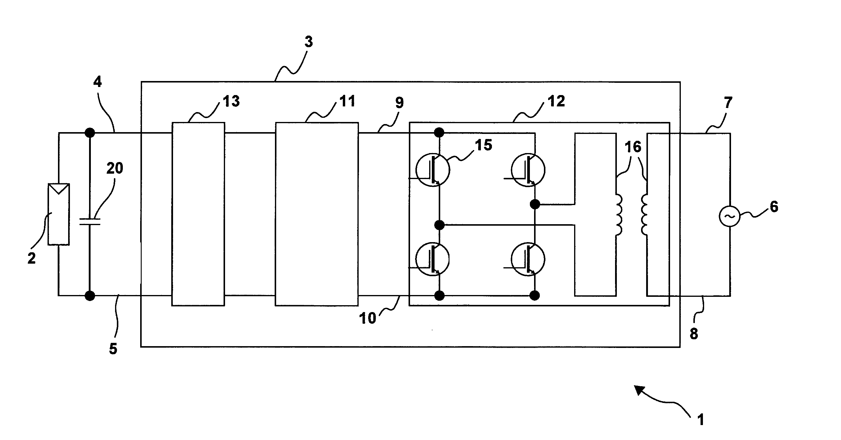
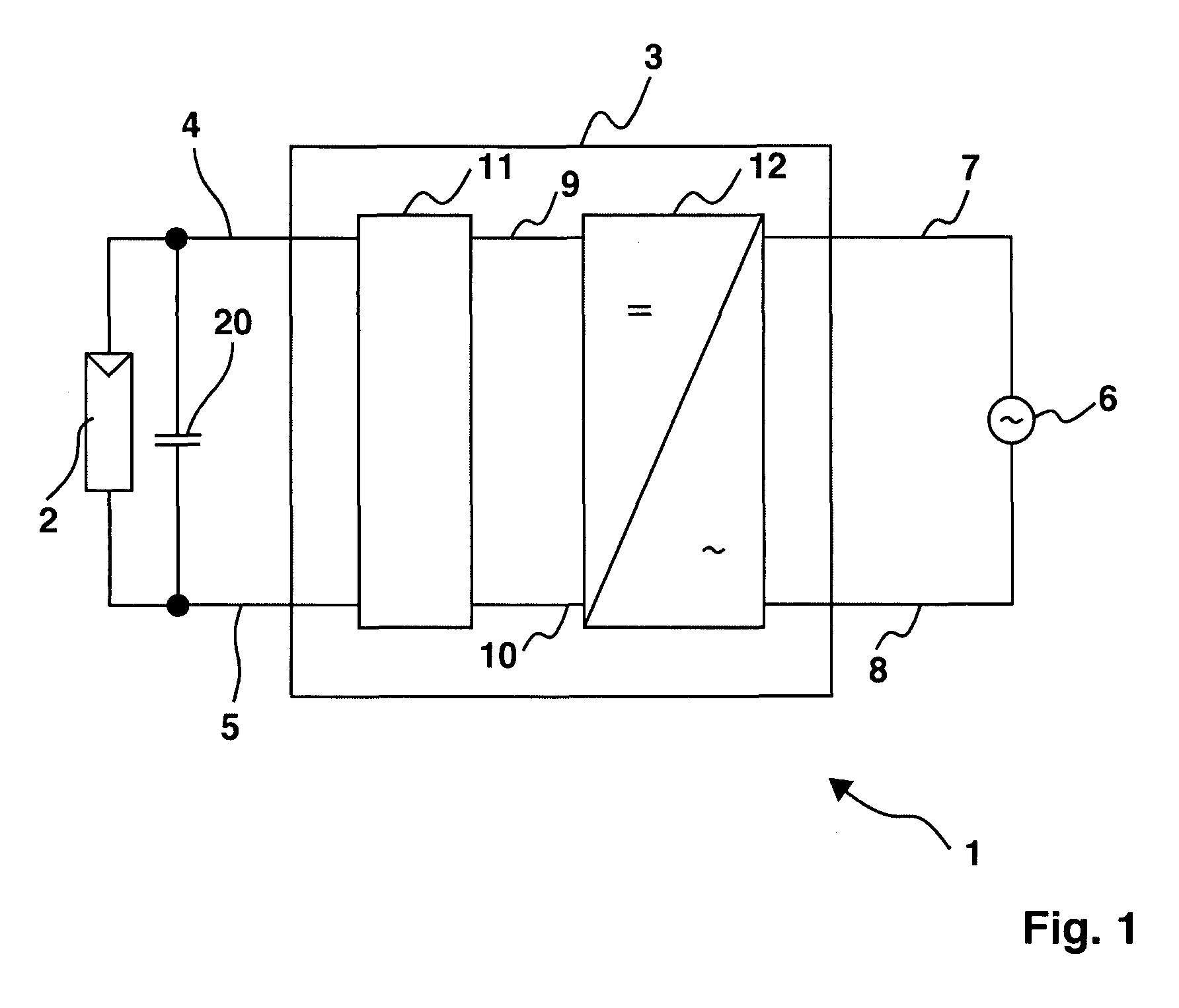
[0037]FIG. 1 illustrates a photovoltaic plant 1. It comprises a generator 2 that is implemented as a photovoltaic generator. It may consist of several modules. Here however, only one is shown. The photovoltaic generator 2 is connected to an inverter 3 through connection terminals 4, 5. A direct voltage is applied to the terminals 4, 5. The inverter 3, which consists of an intermediate circuit 11 and of a DC-AC converter 12, is connected to a power supply network 6, more specifically to a low-voltage network. The connection terminals 7, 8 serve as an alternating voltage network output. The intermediate circuit 11 and the DC-AC converter 12 are connected together through the connection terminals 9 and 10. The photovoltaic generator 2 has an internal capacitance that is shown as the capacitor 20. The DC-AC converter 12 may for example be implemented as a DC-DC-AC converter.

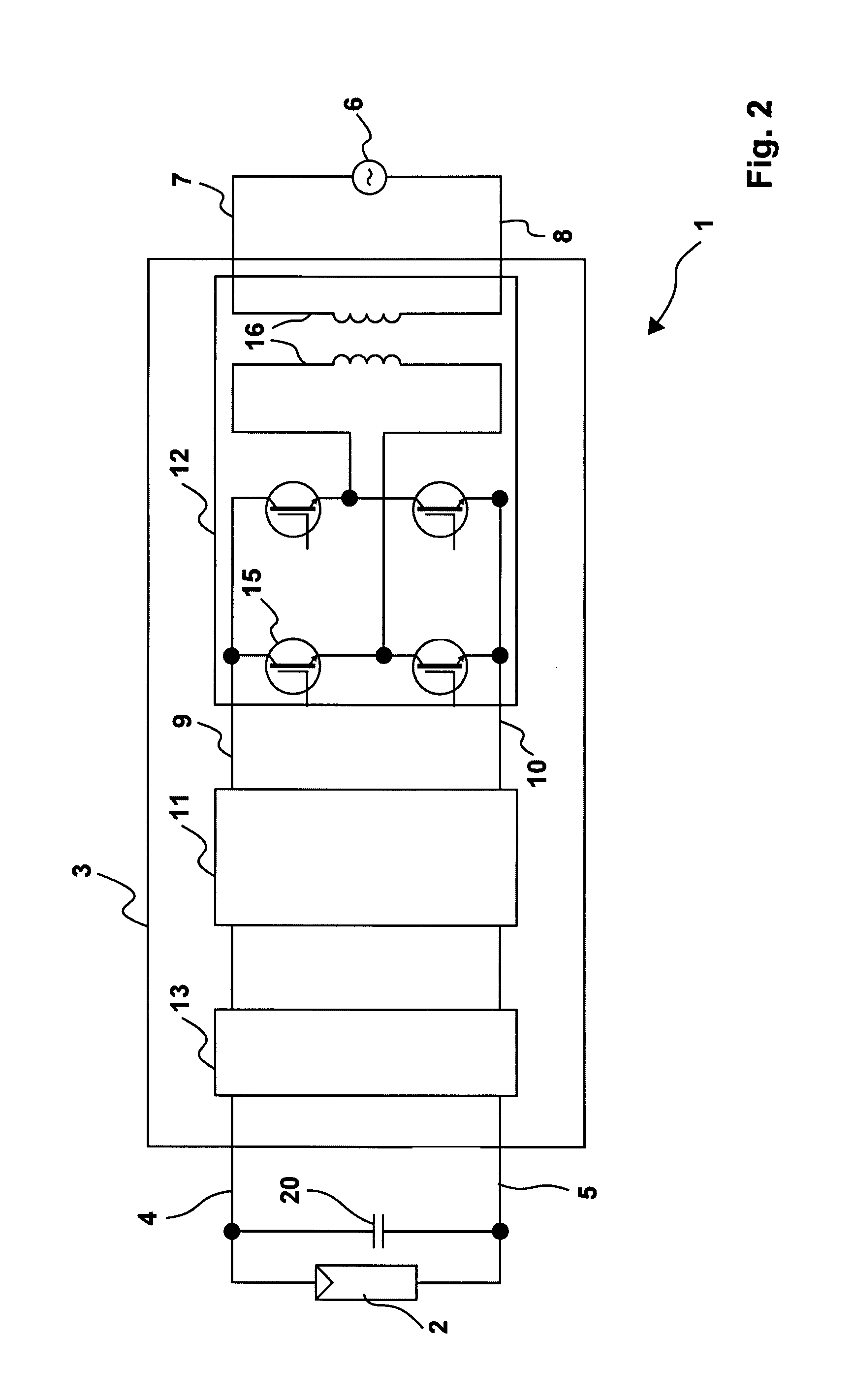
[0038]FIG. 2 shows a photovoltaic plant 1 wi...


PUM


Abstract

The subject matter of the invention is an inverter (3), more specifically for use in a photovoltaic plant (1) with a direct voltage input (connection terminals 4; 5) for connection to a generator (2) and an alternating voltage output (connection terminals 7; 8) for feeding into an energy supply network (6) as well as with a DC-AC converter (12) with semiconductor switch elements (15) and an intermediate circuit (11), at least one short-circuit switch element (18) being connected in parallel to the generator (2), so that the voltage will not exceed a maximum voltage value neither at the connection terminals (4; 5) of the generator (2) nor between the connection terminals (9; 10) of the inverter. This is achieved in that the inverter (3) comprises, in the intermediate circuit (12), a buffer capacitor (14) that is connected to the generator (2) through a protection diode (17) so that said buffer capacitor (14) will not be discharged upon actuation of the short-circuit switch element (18), the generator (2) working according to a clock rate in the short-circuit mode of operation.

Description

FIELD OF THE INVENTION[0001]The invention relates to an inverter, in particular for use in a photovoltaic plant with a direct voltage input for a photovoltaic generator and with an alternating voltage output for feeding for example into an energy supply network as well as with a DC-AC converter with semiconductor switch elements, as well as to a method for overvoltage protection, in particular of a photovoltaic plant with an inverter of the invention.BACKGROUND OF THE INVENTION[0002]Photovoltaic plants for generating electric power include a solar inverter comprising for example a semiconductor bridge converting the direct voltage generated by a solar generator into an alternating voltage.[0003]In the solar inverters, when the bridge is being synchronized, the full voltage of the solar generator is applied to the individual semiconductors. When the solar inverter is ideally fed without interruption over the entire day, the semiconductors could be set to a voltage referred to as an M...

Claims


Application Information

Patent Timeline
Patent Type & Authority Patents(United States)
IPC IPC(8): H02H7/122
CPCH02H7/1222Y10S323/906
Inventor MULLER, BURKHARDGREIZER, FRANK
Owner SMA SOLAR TECH AG
Why Eureka
Try Eureka