Low-voltage IC-circuit

a low-voltage ic-circuit and low-voltage technology, applied in the direction of constant-current supply dc circuit, electric variable regulation, automatic control of pulses, etc., can solve the problems of redundant switching activities, power being wasted for nothing, and inability to ensure that the subcircuit's respective current drain always matches, etc., to achieve uniform voltage drop, stabilize voltage, and reduce energy loss.

Inactive Publication Date: 2010-05-04
BERNAFON
View PDF4 Cites 12 Cited by
  • Summary
  • Abstract
  • Description
  • Claims
  • Application Information

AI Technical Summary

Benefits of technology

[0007]In this way it becomes possible to drive the sub-circuits with very little energy loss, and further this allows balanced voltages to be obtained with no control loops and without complicated activity monitoring and / or adjusting mechanisms in the means for maintaining a uniform voltage drop. The provision of the buffer capacitors will help to stabilize the voltage over the two sub-circuits by absorbing fast transients in the current consumption. The alternately coupled bucket capacitor is a very simple and elegant way of maintaining a uniform voltage drop over the two buffer capacitors and, hence, also the two sub-circuits. Also this solution recycles excess energy and is thus an energy-efficient way of balancing the voltage drops across the two power-consuming workload sub-circuits. In fact, losses would be almost zero were it not for voltage drops across the transistors that act as switches.
[0008]In an alternative embodiment of the invention, there are two bucket capacitors that get switched at the same time such as to alternately couple to the first and the second buffer capacitor respectively. This solution is somewhat more complicated than the solution with only one bucket capacitor, but on the other hand it will assure an even smaller ripple in the supply voltages to the two sub-circuits.
[0009]Preferably the switches for alternately coupling the bucket capacitors are controlled by a free-running oscillator, a clock, or some other suitable signal that toggles at a sufficient rate to allow for a near-perfect voltage balance. Having the switching occur in an autonomous manner is sufficient because of the self-regulatory function of the stabilizer circuit and is a great advantage over more complex schemes that involve control loops. The simplicity keeps the necessary circuit overhead down and should make it possible to design cheaper IC units.

Problems solved by technology

Yet, however much care is taken in the prior art technique, it cannot be ensured that the subcircuit's respective current drains always match.
Any imbalance implies that power is being wasted for nothing.
This is because an imbalance either causes one or more of the regulators to carry a nonzero current or gives rise to redundant switching activities.
In fact, losses would be almost zero were it not for voltage drops across the transistors that act as switches.

Method used


Image

  • Low-voltage IC-circuit
  • Low-voltage IC-circuit
  • Low-voltage IC-circuit

Examples


Embodiment Construction

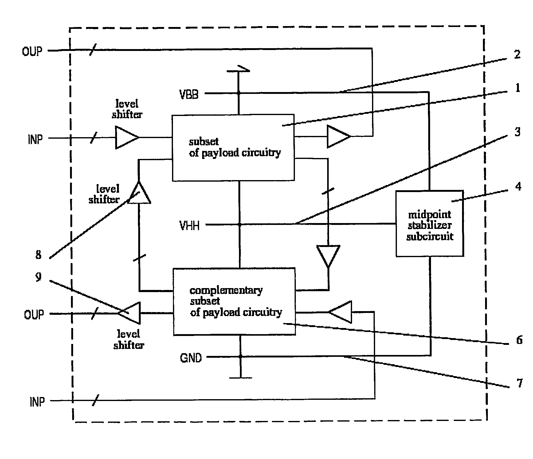
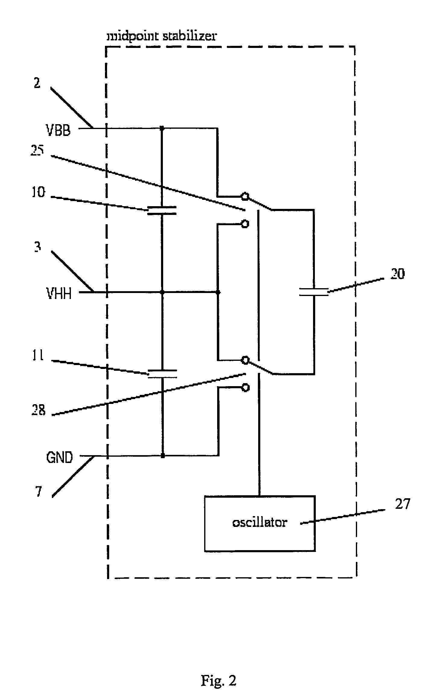
[0015]The overall circuit organization is shown in FIG. 1. Here two complementary subsets of the payload circuit are connected in series. The first sub-circuit 1 of the payload circuitry has a power supply line 2, which maintains the voltage level of VBB and a ground connection 3, which is to maintain voltage level VHH. The ground connection 3 is also routed to the midpoint stabilizer 4 and functions as power supply line to the further sub-circuit 6 of the payload circuitry. This sub-circuit 6 further has a ground connection 7 with the voltage level of GND. The midpoint stabilizer 4 ensures that the voltage in the power supply line 3 that connects sub-circuit 1 to sub-circuit 6 remains constant and at the midpoint between the battery supply voltage VBB and the ground level GND. Level shifters 8 are mandatory wherever a signal crosses over from the lower partition to the upper partition or vice versa. Depending on the peripheral voltage levels, level-shifters 9 are likely to be requi...


PUM


Abstract

An integrated circuit is partitioned into two or more sub-circuits, each sub-circuit including two supply terminals across which to receive supply voltage. The sub-circuits are connected in series with the first sub-circuit receiving input voltage at its first supply terminal, and the voltage level output at the second supply terminal of the first sub-circuit being used as input voltage level in a second sub-circuit. Further, a control-circuit is configured to balance voltage drops across the sub-circuits and to maintain constant voltage-drops over the sub-circuits. The control-circuit includes two buffer capacitors, each coupled in parallel over one of the two sub-circuits respectively. The control-circuit also includes at least one bucket capacitor alternately coupled in parallel over the first and the second buffer capacitor through a switching system controlled by a toggling signal.

Description

BACKGROUND OF THE INVENTION[0001]Starting with the 0.35 μm generation, CMOS scaling has changed from a constant-voltage regime with a nominal supply voltage of 5V to a constant-field regime where the supply voltage is being reduced in concert with geometric dimensions with each process generation. We are thus likely to see more and more CMOS circuits in the future that must operate with a supply voltage below that of the usual sources of electrical energy. As an example, consider a 1.2V battery cell that feeds a low-power low-voltage circuit operating at a mere 0.6V. The most obvious solution is to use a voltage converter in down mode. While this is possible, the converter is costly, space consuming, and also has its own power dissipation. Partitioning the overall IC into two or more sub-circuits and connecting them in series does away with the down converter because the IC can so be powered from a supply with a higher voltage than what is suitable for an individual sub-circuit. U.S...

Claims


Application Information

Patent Timeline
Patent Type & Authority Patents(United States)
IPC IPC(8): G05F3/02H02J1/10G05F3/04H02J1/00H02J7/00H03L5/00
CPCH01L23/5286H01L2924/0002H01L2924/00
Inventor KAESLIN, HUBERTFELBER, NORBERT
Owner BERNAFON
Why Eureka
Try Eureka