Torque transmitting unit and drive train for it

a transmission unit and drive train technology, applied in mechanical actuated clutches, fluid gearings, gearings, etc., can solve the problems of high output and consume large amounts of energy, and achieve the effect of reducing or eliminating torsional vibrations

Active Publication Date: 2005-06-30
SCHAEFFLER TECH AG & CO KG
View PDF9 Cites 53 Cited by
  • Summary
  • Abstract
  • Description
  • Claims
  • Application Information

AI Technical Summary

Benefits of technology

[0020] To reduce or eliminate torsional vibrations migrating from the internal combustion engine into the transmission, a dual-mass flywheel disposed between crankshaft and input part of the two friction clutches may be provided on the torque transmission device. This dual-mass flywheel may be integrated into the chamber filled with hydraulic fluid or be mounted outside the chamber. The dual-mass flywheel may also form a part of the housing for the chamber and/or have a drive part for the pump. The holding of the dual-mass flywheel on the crankshaft may be accomplished via an axially flexible disk part of a so-called “flexplate”. Of course, the torque transmission device without a dual-mass flywheel may also be held in this manner on the crankshaft. It may be especially advantageous, in conjunction with the mass ratios of a twin clutch, to form two masses that swivel against at least an energy accumulator acting in the circumferential direction and are on the driven and driving side of the flywheel so that they are coupleable with each other at least temporarily, the coupling being accomplished via a friction device that depends on centrifugal force. The use of a coupling with mass ratios in which the driving side moment of inertia is greater than that of the driven side may be especially advantageous, for example, a first coupleable mass having a moment of inertia of 0.1±0.04 kgm2 on the driving side and a second mass on the driven side has a moment of inertia of 0.04+0.04 kgm2. It has also proven advantageous to sustain the two masses up to a range from 1200 to 1800 rpm.
[0021] The assembly of the torque trans

Problems solved by technology

Pumps of this type have high outputs and c

Method used


Image

  • Torque transmitting unit and drive train for it
  • Torque transmitting unit and drive train for it
  • Torque transmitting unit and drive train for it

Examples


Embodiment Construction

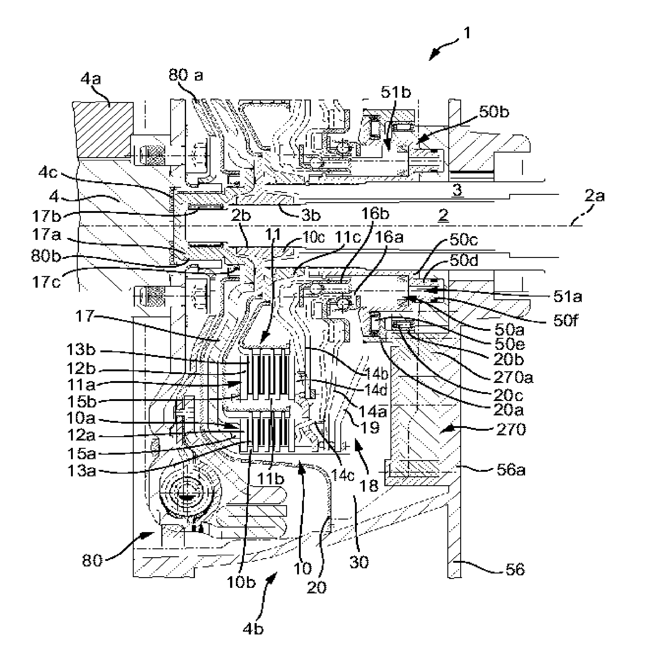
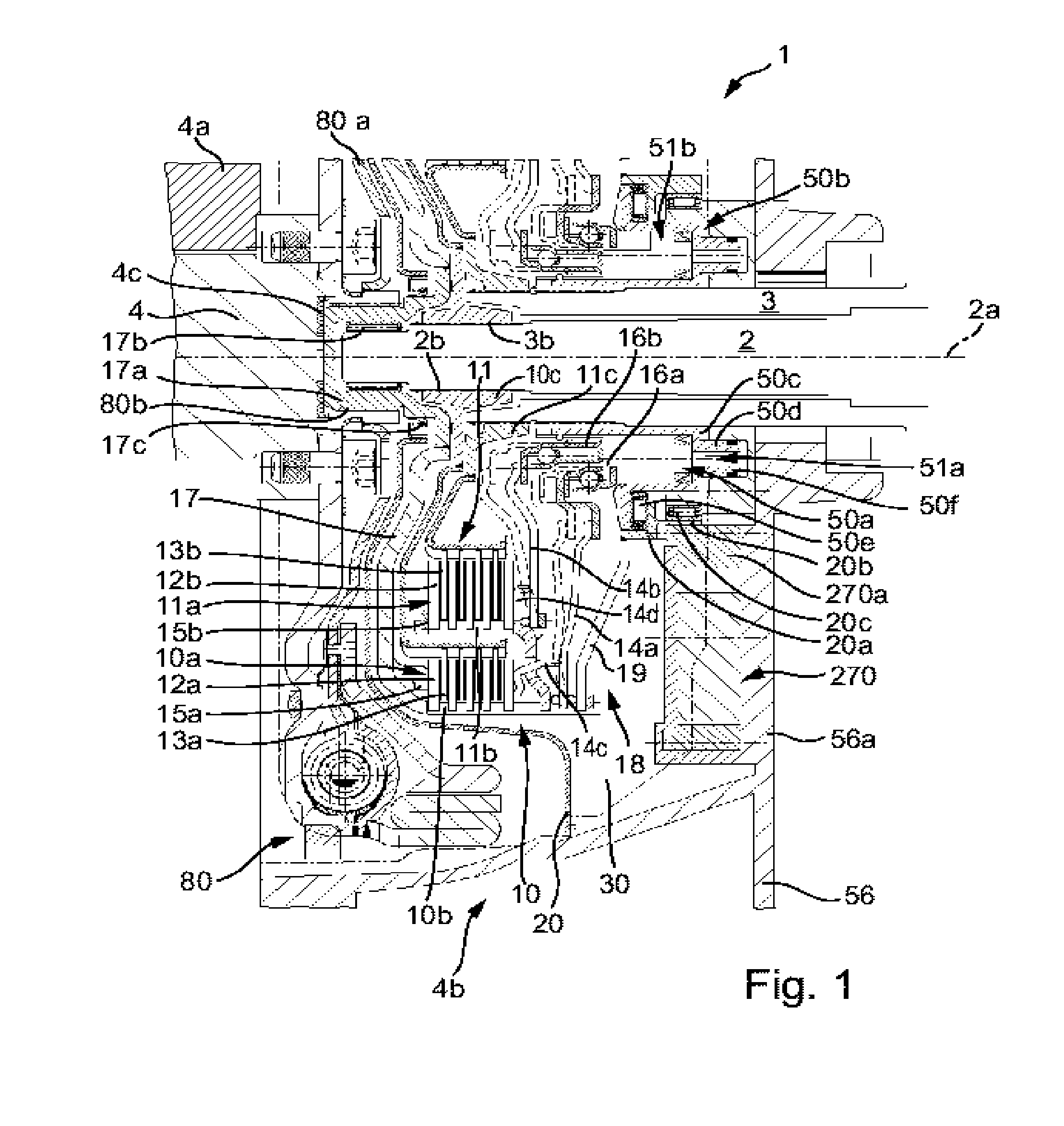
[0035]FIG. 1 shows a partial section of a torque transmission device 1 as a twin clutch in the drive train of a motor vehicle, comprising a drive unit (not shown) having a crankshaft 4 swivel-mounted in a wall 4a of the engine housing and a twin-clutch transmission having a first transmission shaft 2 rotating about a rotational axis 2a and a second transmission input shaft 3 that is formed in the shown exemplary embodiment as a hollow shaft. Torque transmission device 1 is housed in a so-called clutch bell housing 4b, which together with wall 4a forms an enclosed space. Torque transmission device 1 is subdivided into two friction clutches 10, 11 having friction units 10a and 11a disposed radially one over the other. Each friction clutch 10, 11 is rotationally connected via an input part 10b, 11b to crankshaft 4 and via an output part 10c, 11c to one transmission input shaft 2, 3 each. In the power flow between input parts 10b, 11b and output parts 10c, 11c, the two clutches 10, 11 a...


PUM


Abstract

The invention relates to a torque transmission device, especially for a drive train comprising an internal combustion engine and a twin-clutch transmission having two transmission input shafts and one transmission output shaft, each transmission input shaft being connectable to an internal combustion engine via a clutch of the torque transmission device.

Description

CROSS-REFERENCE TO RELATED APPLICATION [0001] This patent claims priority of German Patent Application No. 103 61 491.5, filed Dec. 23, 2003, which application is incorporated herein by reference. BACKGROUND OF THE INVENTION [0002] The invention relates to a torque transmission device, especially for a drive train comprising an internal combustion engine and a twin-clutch transmission having two transmission input shafts and one transmission output shaft, each transmission input shaft being connectable to an internal combustion engine via a clutch of the torque transmission device. [0003] Twin clutch transmissions having two transmission input shafts are known in which a torque transmission device has one wet clutch for each transmission input shaft, the wet clutches being hydrostatically actuated via suitable piston units and the pressure needed for this purpose, and in some cases the pressure for cooling the clutches when necessary, being generated by a hydraulic fluid pump. Pumps...

Claims


Application Information

Patent Timeline
IPC IPC(8): F16D25/10F16F15/134F16D25/12F16D28/00F16D48/02F16F15/131F16F15/31F16H45/02
CPCF16D25/10F16D25/123F16F15/13135F16D2023/126F16D48/02F16D2048/0236F16D48/0206F16D2048/0209F16D2500/1024F16D2500/10412F16D2500/1045F16D2021/0661F16D25/08F16H45/02F16D21/06
Inventor AGNER, IVOREIK, WOLFGANGWERNER, OLAF
Owner SCHAEFFLER TECH AG & CO KG
Why Eureka
Try Eureka