Sheet material shaping apparatus

a technology of shaping apparatus and sheet material, which is applied in the field of shaping apparatus, can solve the problems of inconvenient adjustment of the gap between the shaping rolls, inability to form three-dimensional shapes on the sheet material, and inability to meet the needs of patients, etc., and achieves the effect of easy positioning of the shaping roll, easy adjustment of pressing force and the like, and uniform and easy formation

Active Publication Date: 2015-11-17
ZUIKO CORP
View PDF12 Cites 0 Cited by
  • Summary
  • Abstract
  • Description
  • Claims
  • Application Information

AI Technical Summary

Benefits of technology

[0024]Constituted and functioning as described above, the present invention produces the following effects.
[0025](1) In Aspect 1 of the present invention, a shift of the shaping roll can be absorbed by the eccentric joint, and the output shaft of the rotational driving means to the shaping roll can be positioned at a predetermined position. As a result, positioning of the shaping roll is easy, and the gap between the rolls, the depth of meshing, the pressing force and the like can be adjusted easily; thus, a large number of fine three-dimensional shapes can evenly and easily be formed on a sheet material.
[0026](2) In Aspect 2 of the present invention, since a sheet material is prevented from being lifted from the circumferential surface of the downstream shaping roll in the first preset region, the three-dimensional shapes that have been formed on the sheet material can be held by the recessed and protruding shapes on the circumferential surface of the roll; thereby their shapes can be sustained well. Also, since the sheet material can be pushed in such a manner as to be separated from the circumferential surface of the roll by the air supplied from the air supply means in the second preset region, the three-dimensional shapes that have been formed on the sheet material can be surely taken out of the recessed and protruding shapes on the circumferential surface of the roll, and thus be easily separated from the circumferential surface of the roll. As a result, a large number of fine three-dimensional shapes can rapidly and minutely be formed on a sheet material.

Problems solved by technology

Then, in a case where output sections of the transmission device are directly coupled to the rotating shafts of the shaping rolls, the output shafts of the rotational driving means should also be shifted together with the shaping rolls being shifted, which is not easy.
Besides, even a slightly oblique deflection of the roll shaft centers of the pair of shaping rolls from their parallel disposition results in differences in the gap between the rolls, the depth of meshing, the pressing force and so forth between one end and the other end of the shaping rolls, thereby causing a problem that three-dimensional shapes formed on the sheet material become nonuniform.
Therefore, the gap between the rolls, etc. must be adjusted minutely, which has been very troublesome.
As a result, there is a risk that the sheet material, after passed between the pair of shaping rolls and conveyed on the circumferential surface of the downstream shaping roll to the next process is lifted off the roll surface having the recessed and protruding shapes due to a centrifugal force and thereby cannot maintain the predetermined three-dimensional shapes; and there is also a risk that, if there is a deviation of the three-dimensional shapes on the sheet material from the recessed and protruding shapes on the surface of the shaping roll, the three-dimensional shapes on the sheet material become deformed when pressed by the pressing roll disposed on the downstream side.
Further, in a case where the three-dimensional shapes that are formed on the sheet material tightly fit the recessed and protruding shapes that are formed on the downstream shaping roll, it is not easy to separate the sheet material from the surface of the downstream shaping roll at the position where the sheet material is sent out to the next process; this may place an obstacle to sending it out to the next process and thus increases the risk that the sheet material winds around the downstream shaping roll.
Thus, there has been a problem that, with use of the conventional shaping apparatus, sufficiently high shaping speed of three-dimensional shapes is not easily attained.

Method used


Image

  • Sheet material shaping apparatus
  • Sheet material shaping apparatus
  • Sheet material shaping apparatus

Examples


Embodiment Construction

[0034]The present invention is concretely described below, referring to the drawings.

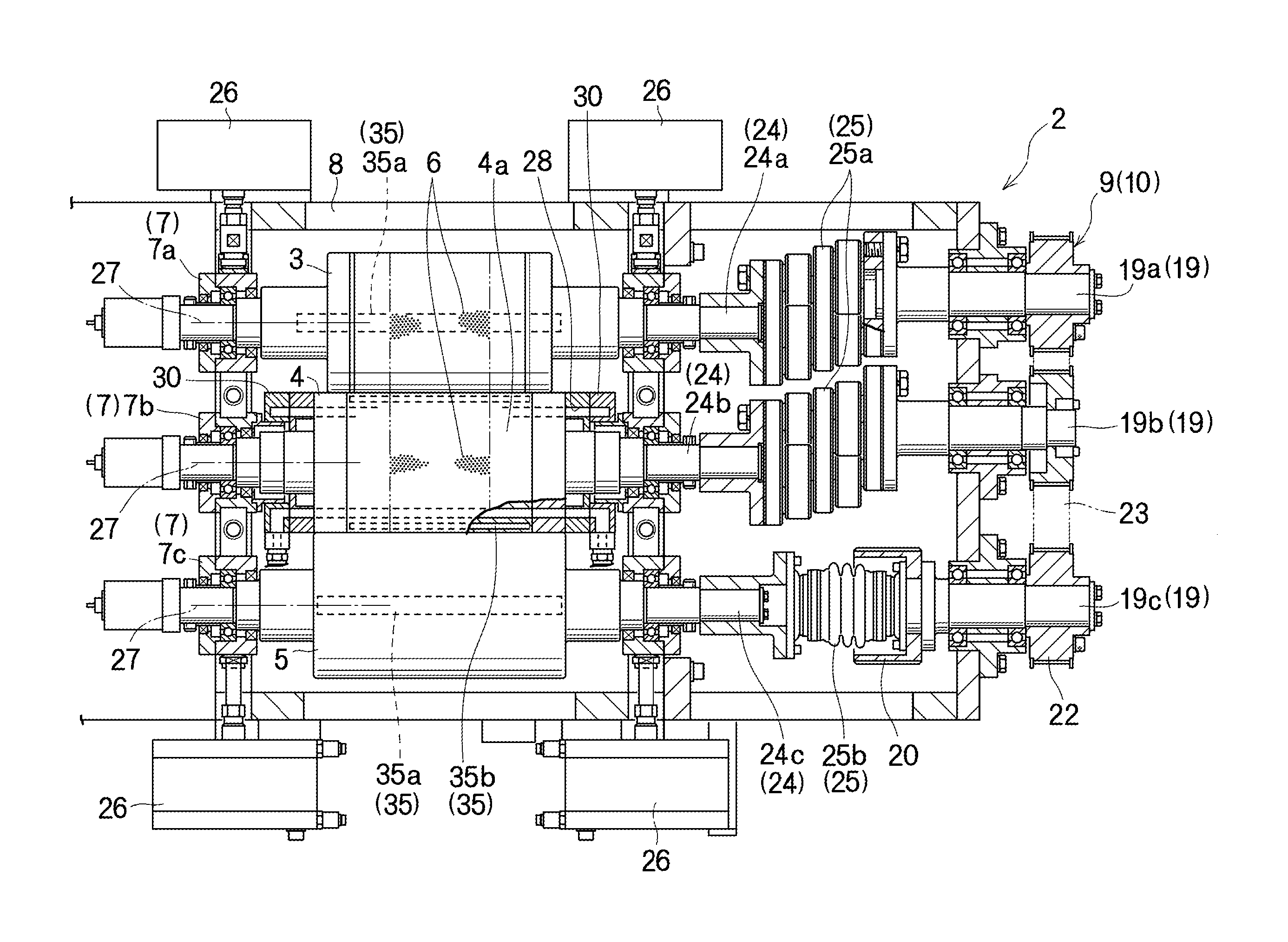
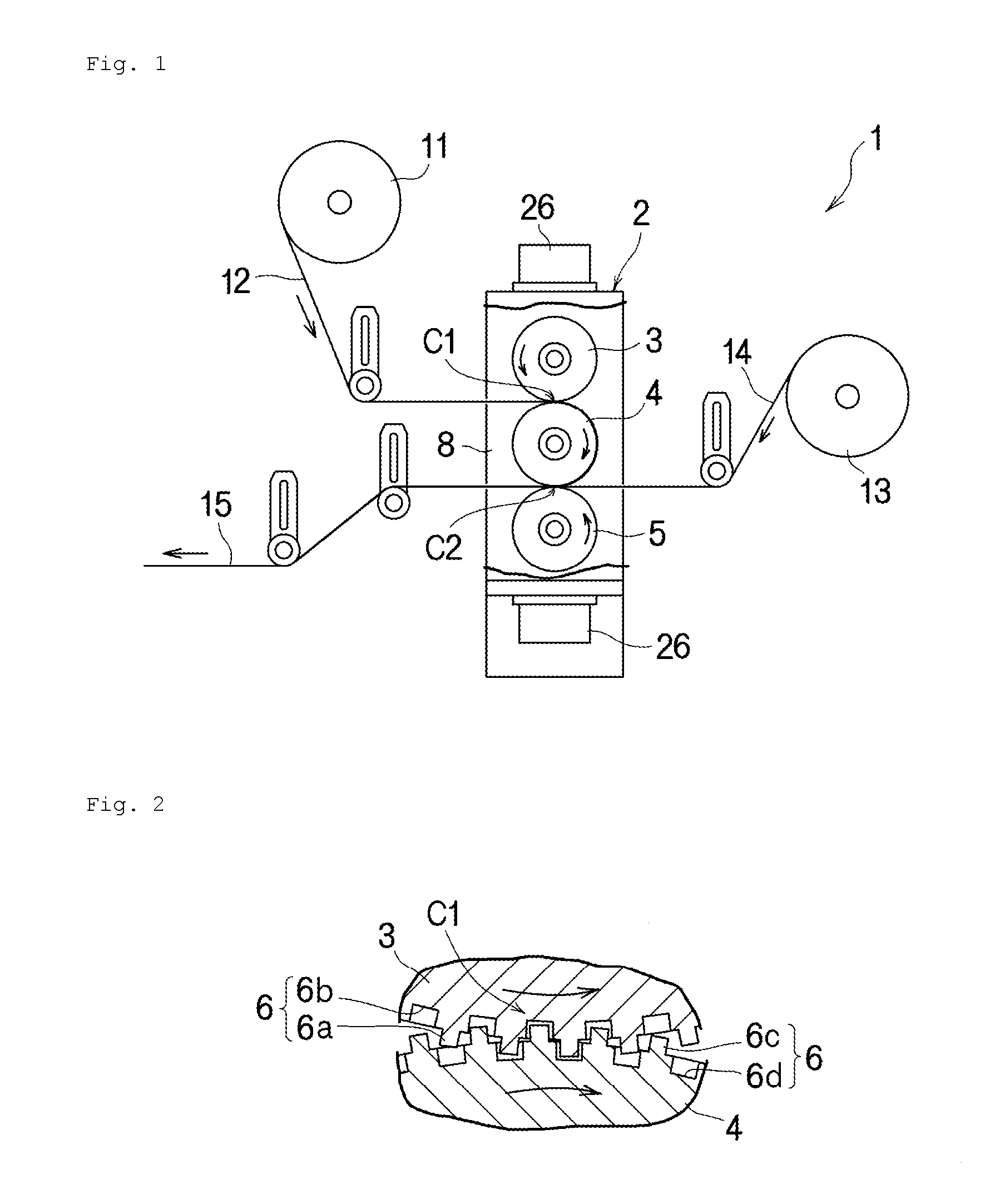
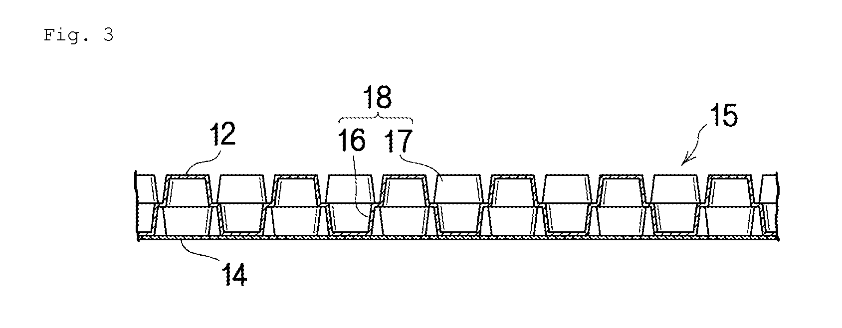
[0035]FIG. 1 is a drawing showing a general configuration of a composite sheet production apparatus (1) comprising a shaping apparatus (2) according to an embodiment of the present invention; by the shaping apparatus (2), a first sheet material (12) that is supplied from a first feed section (11) and a second sheet material (14) that is supplied from a second feed section (13) are joined together to produce a composite sheet (15).

[0036]The shaping apparatus (2) includes a pair of shaping rolls (3, 4), and a pressing roll (5) disposed thereunder; the rolls (3, 4, 5) are disposed, as shown in FIG. 4, in such a manner that respective roll shaft centers (27) are parallel to each other.

[0037]The pair of shaping rolls (3, 4) face each other at a first face-to-face section (C1), and the shaping roll (4) on the lower side and the pressing roll (5) face each other at a second face-to-face section (C2). The f...


PUM

PropertyMeasurementUnit
diameteraaaaaaaaaa
surface velocityaaaaaaaaaa
thicknessesaaaaaaaaaa

Abstract

The invention relates to positioning of shaping rolls and makes it possible the rapid formation of a large number of fine three-dimensional shapes on a sheet material. A pair of shaping rolls that are parallel to each other include, on circumferential surfaces thereof, recessed and protruding shapes that mesh with each other at a face-to-face position. Rotating shafts of the pair of shaping rolls are cooperatively coupled with a rotational driving means through eccentric couplings. A downstream shaping roll includes, inside a roll main body, air passages that extend in a direction of a roll shaft center and air vent holes that connect the air passages to the circumferential surface. A communication member is disposed adjacent to the end of the roll main body and includes an air intake port that can communicate with the air passages in a first preset region in a circumferential direction, and an air supply port that can communicate with the air passages in a second preset region. The air intake port is communicably connected to an air intake means, and the air supply port is communicably connected to an air supply means.

Description

TECHNICAL FIELD[0001]The present invention relates to a shaping apparatus for sheet materials used for surface sheets for absorbent articles and / or the like, such as disposable diapers and sanitary napkins, and more specifically, to a shaping apparatus capable of forming a large number of fine three-dimensional shapes on a sheet material rapidly and minutely.BACKGROUND ART[0002]Among the surface sheets for the absorbent articles are those using a composite sheet that is made by laying a sheet material on which a large number of protruding portions are formed on top of a smooth sheet material and joining the two sheet materials at positions in between the protruding portions. The composite sheet is to be worn in such a manner that the large number of protruding portions protrude toward the skin of a wearer, thereby providing a feeling of comfort to wear as well as preventing liquid leakage effectively.[0003]Conventionally, as a shaping apparatus forming a large number of three-dimens...

Claims


Application Information

Patent Timeline
Patent Type & Authority Patents(United States)
IPC IPC(8): B29C43/46A61F13/15B29C51/22B29C51/08
CPCA61F13/15731B29C51/225A61F2013/15715B29C51/082
Inventor UMEBAYASHI, TOYOSHISHIMADA, TAKAHIRO
Owner ZUIKO CORP
Why Eureka
Try Eureka