

Apparatus for detecting impurities in material and detecting method therefor
a technology for impurities and detectors, applied in the field of impurity detection apparatuses, can solve the problems of hard to detect impurities and cannot be detected practically, and achieve the effect of accurately detecting impurities in other bulk materials and accurately detecting impurities in materials
- Summary
- Abstract
- Description
- Claims
- Application Information
AI Technical Summary
Benefits of technology
Problems solved by technology
Method used
Image

Examples
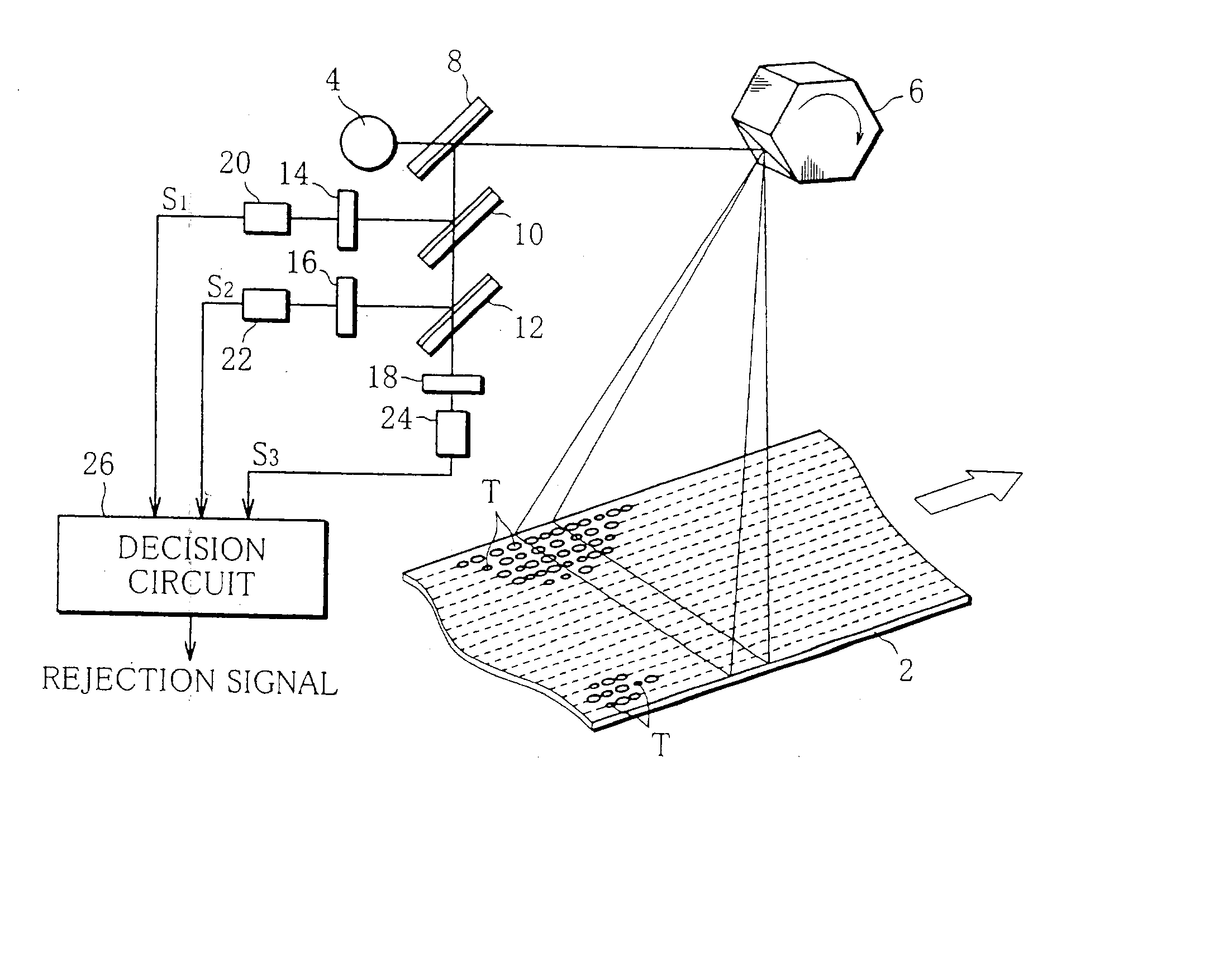
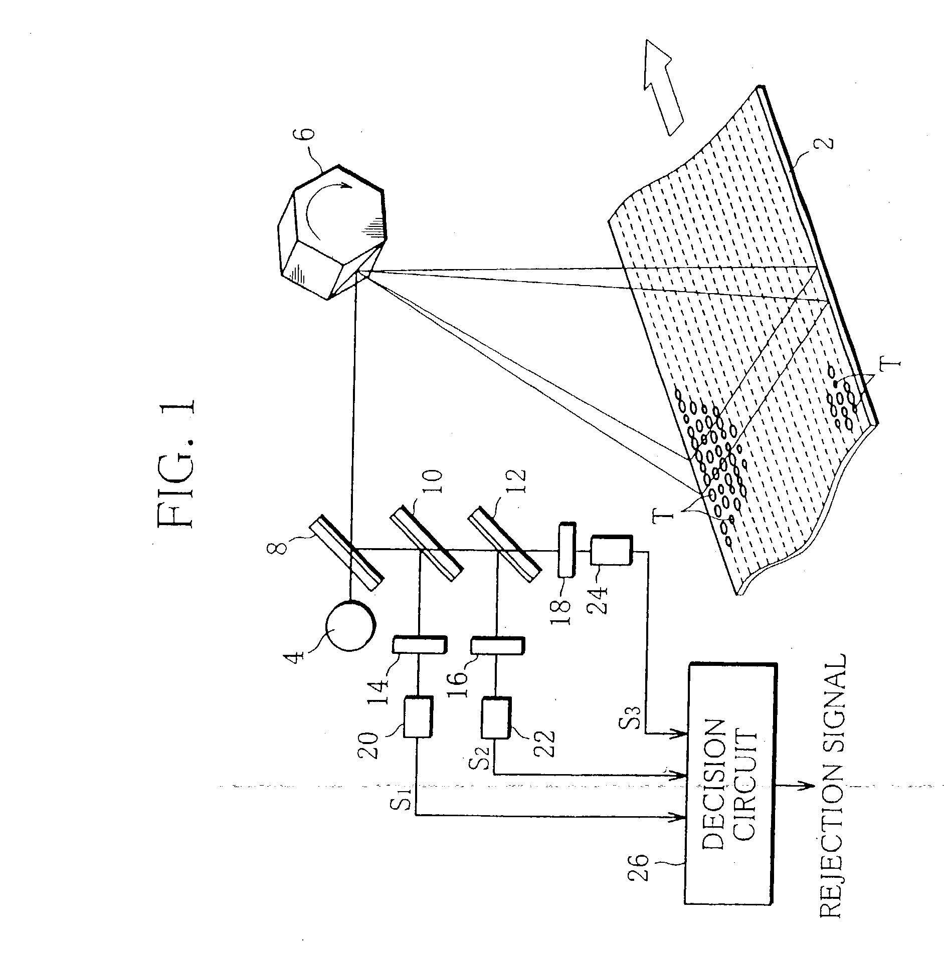
first embodiment
[0053] In the case of the detecting apparatus of the foregoing first embodiment, the same path is used for the transmission of the infrared rays to the material T and the transmission of the reflected infrared rays from the material T, so that the provided detecting apparatus is compact.
second embodiment
[0054] Then, FIGS. 4 and 5 a detecting apparatus and a detecting method of a
[0055] The detecting apparatus of the second embodiment comprises an infrared camera 36 over the conveyor 2. The infrared camera 36 has a range that covers the overall width of the conveyor 2, and its internal configuration is specifically shown in FIG. 5. The infrared camera 36 has a camera lens 38. The camera lens 38 converges the reflected infrared rays from the material T on the conveyor 2, and supplies the reflected infrared rays to a dichroic mirror 42.
[0056] The dichroic mirror 42 transmits and directs some of the reflected infrared rays from the camera lens 38 toward the first band-pass filter 14, and on the other hand, deflects the remainder toward a dichroic mirror 44. Further, the dichroic mirror 44 transmits and directs some of the reflected infrared rays from the dichroic mirror 42 toward the second band-pass filter 16, and on the other hand, deflects the remainder toward the third band-pass fil...
third embodiment
[0060] Then, FIGS. 6 to 8 show a detecting apparatus and a detecting method of a
[0061] The detecting apparatus of the third embodiment comprises a housing 60, and the housing 60 contains an infrared generator 62 therein. The infrared generator 62 may include, for example, a halogen lamp, sodium lamp, or infrared heater.
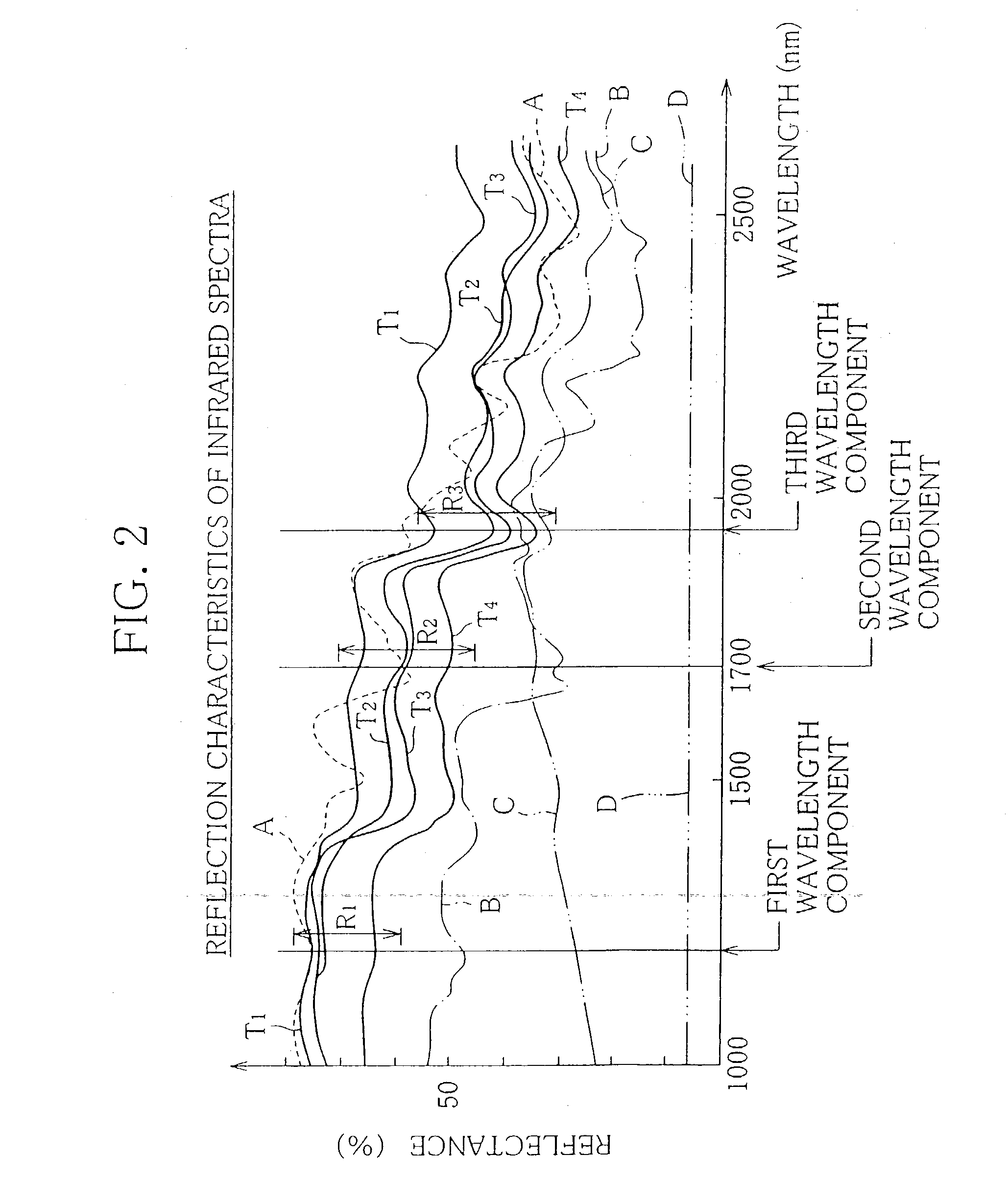
[0062] Infrared rays generated from the infrared generator 62 are transmitted through first to third band-pass filters 64, 66 and 68 and emitted toward their corresponding optical fibers 70, individually. The first to third band-pass filters 64, 66 and 68 can receive only the aforesaid first to third wavelength components of the infrared rays, and guide the received wavelength components to their corresponding optical fibers 70.
[0063] The optical fibers 70 are connected optically to a joint 72, and two optical fibers 74 extend from the joint 72. Thus, only the three specified wavelength components of the infrared rays generated from the infrared generator 62 are guide...
PUM
 Abstract
Description
Claims
Application Information