Power converting device

A power conversion device and voltage technology, applied in high-efficiency power electronic conversion, output power conversion devices, electrical components, etc., can solve problems such as ripple voltage

Inactive Publication Date: 2002-12-04
TDK CORPARATION
View PDF2 Cites 12 Cited by
  • Summary
  • Abstract
  • Description
  • Claims
  • Application Information

AI Technical Summary

Problems solved by technology

This control method is accompanied by the problem that ripple voltage is generated in the case of causing the power conversion device to perform inverter operation
If a capacitor is used for downsizing the dev...

Method used


Image

  • Power converting device
  • Power converting device
  • Power converting device

Examples


Embodiment Construction

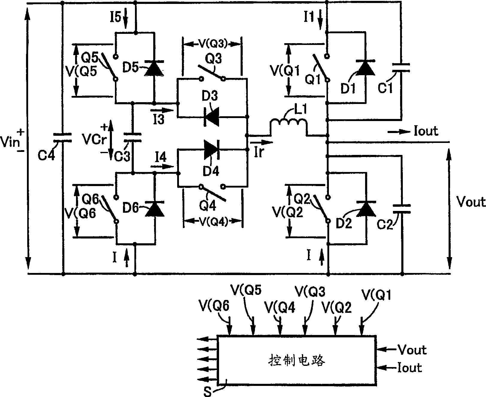
[0040] Hereinafter, embodiments of the present invention will be described with reference to the drawings. figure 1 is a circuit diagram of the first embodiment of the present invention. The circuit includes first and second main switches Q1 and Q2 connected in series, and one main switch Q1 is connected to a DC power supply V inThe positive terminal of the other main switch Q2 is connected to the DC power supply V in negative terminal. A diode D1 is connected in parallel to the main switch Q1, and a diode D2 is connected in parallel to the main switch Q2, so that they are respectively reverse-biased relative to the DC power supply, that is, the forward direction of the diode faces the DC power supply V in positive end. Also, a main switch snubber capacitor C1 is connected in parallel to the main switch Q1, and a main switch snubber capacitor C2 is connected in parallel to the main switch Q2. A capacitor C4 connected in parallel with the main switches Q1, Q2 connected in s...


PUM


Abstract

Disclosed is a power conversion device that does not generate ripples, including a control circuit that generates a switching signal at a timing capable of realizing soft switching. The first main switch (Q1) and the second main switch (Q2) connected in series are connected to the positive terminal of the DC power supply at the end of the first switch, and connected to the negative terminal of the DC power supply at the end of the second main switch. Diodes (D1, D2) are connected in parallel on each main switch to make it reverse biased relative to the DC power supply. On each main switch, the main switch buffer capacitors (C1, C2) are connected in parallel. The connection point of the circuit is connected to the load, and the output is generated by controlling the on and off of the main switch according to the switching signal from the control circuit. The first auxiliary resonant circuit composed of the first auxiliary switch and the second auxiliary switch (Q3, Q4, Q5, Q6) connected in series and the resonant inductor (L1) connected in series on the second auxiliary switch is connected to the positive terminal of the DC power supply Between its connection point and the two main switches, connect diodes to the first and second auxiliary switches so that they are reverse biased relative to the DC power supply. The control circuit takes the voltage signals from the voltage detection part representing the voltages at both ends of the main switch and the above-mentioned auxiliary switch as input, and supplies the first and second auxiliary switches with an on-signal as a switch signal before supplying the first main switch Turn on the signal.

Description

technical field [0001] The present invention generally relates to current conversion devices. More specifically, the present invention relates to a power conversion device including a control circuit capable of realizing soft switching of switching elements. Background technique [0002] In power conversion devices such as converters and inverters, circuits including soft switching functions are being developed for the purpose of reducing switching losses of switching elements and increasing switching frequencies. [0003] For example, in U.S. Patent No. 5,047,913, a converter with the following structure is disclosed: the voltage of the DC power supply is divided into a voltage of 1 / 2 by two capacitors connected in series, and the connection point of the capacitor is passed through a bidirectional switch and an inductor. connected to the connection point of two series-connected main switches. The load is connected to the connection point of the mai...

Claims


Application Information

Patent Timeline
IPC IPC(8): H02M1/12H02M7/48H02M7/523
CPCH02M1/12H02M7/4826H02M7/5233H02M1/0048Y02B70/10
Inventor 田中克明沖口美久伊藤一行
Owner TDK CORPARATION
Why Eureka
Try Eureka