Dielectric filter having an inner conductor with two open-circuited inner ends
a dielectric filter and inner conductor technology, applied in the field of dielectric filters, can solve the problems of difficult mounting of filters, troublesome manipulation, and mounting of dielectric filters of this type on circuit boards
- Summary
- Abstract
- Description
- Claims
- Application Information
AI Technical Summary
Problems solved by technology
Method used
Image

Examples
first embodiment
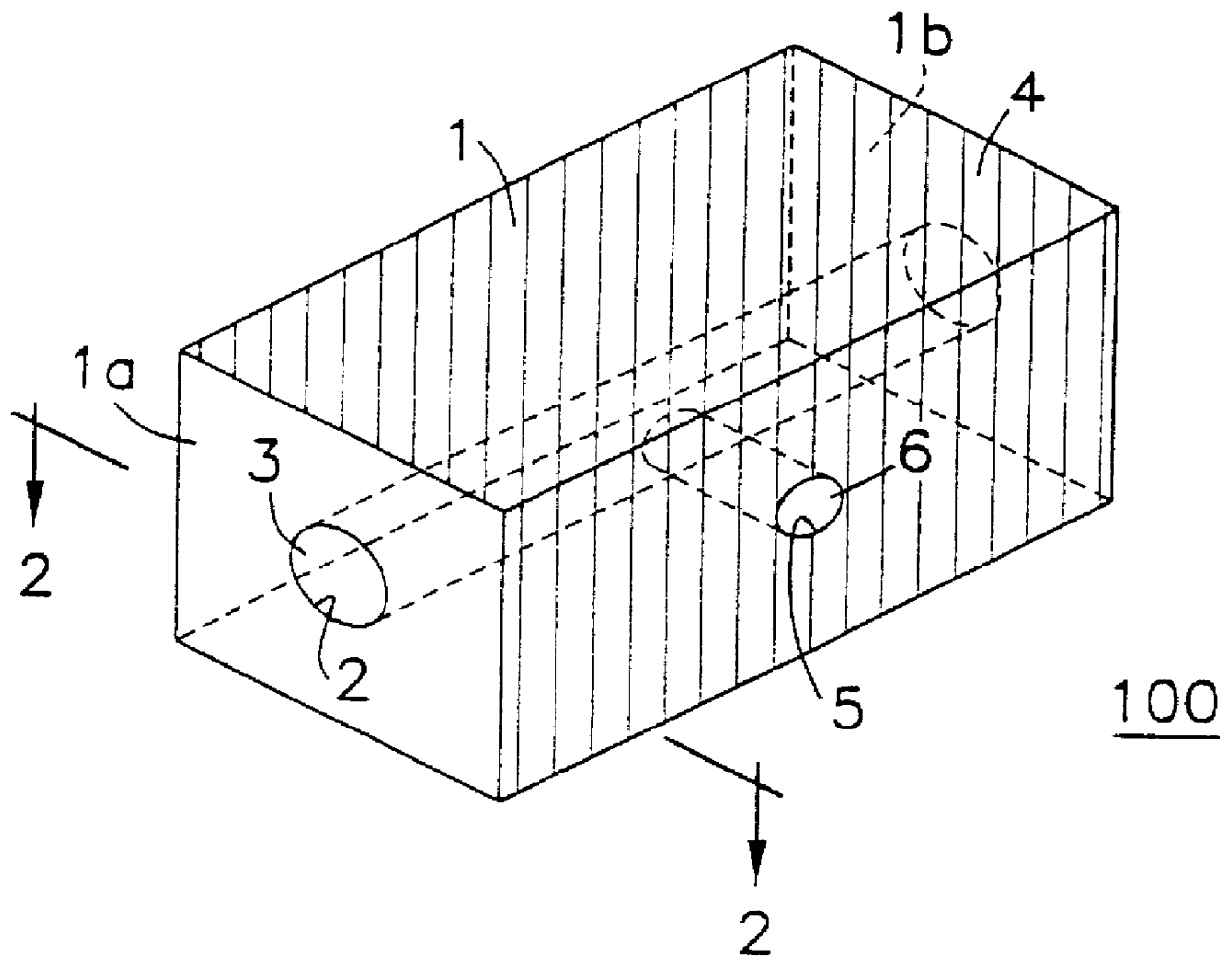
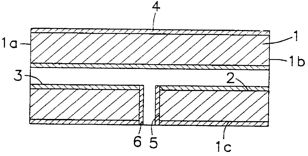
FIG. 1 is a perspective view of a dielectric filter 100 according to the present invention. FIG. 2 is a cross-sectional view taken along line 2--2 of FIG. 1. As shown in these figures, the dielectric filter includes a rectangular dielectric block 1 made up of a ceramic material. The dielectric block 1 has two opposing end faces 1a and 1b. A through-hole 2 is formed between these end faces 1a and 1b. An inner conductor 3 is formed on the inner wall of the through-hole 2. An outer conductor 4 is formed over the whole outer surface of the dielectric block 1 except its end faces 1a and 1b. In this structure, the inner conductor 3 is not connected, at either end, to the outer conductor 4 and thus the inner conductor 3 is electrically open-circuited at both its ends. The inner conductor 3 and the outer conductor 4 may be formed, for example, by disposing an electrode material such as Cu over the whole surface of the dielectric block 1 including the inner wall of the through-hole 2 by mean...
second embodiment
FIG. 8 is a perspective view of a dielectric filter 200 according to the present invention, while a plan view thereof is shown in FIG. 9. As shown in these figures, the dielectric filter is composed of a dielectric block 21 made up of a ceramic material including two sub-blocks LW1 and LW2 formed in an integral fashion. Sub-blocks LW1 and LW2 have equal lengths LE1 and LE2 and equal widths W1 and W2 wherein sub-blocks LW1 and LW2 are shifted in position along their longitudinal directions relative to each other by half the length LE1 or LE2.
The sub-block LW1 has two opposing end faces, namely a first end face 21a and a second end face 21b, located at either end of the length LE1, and also has two opposing sides, namely an upper face 21c and a lower face 21d, which are perpendicular to the end faces 21a and 21b. Similarly, the sub-block LW2 has two opposing end faces, namely a first end face 21e and a second end face 21f, located at either end of the length LE2, and also has two oppo...
third embodiment
FIG. 12 is a perspective view of a dielectric filter 300 according to the present invention, while a plan view thereof is shown in FIG. 13. As shown in these figures, the dielectric filter is composed of a dielectric block 41 made up of a ceramic material including three sub-blocks LW3, LW4, and LW5 which are formed in an integral fashion. Sub-blocks LW3, LW4, and LW5 have equal lengths LE3, LE4, and LE5, respectively, and equal widths W3, W4, and W5, respectively. Sub-blocks LW3, LW4, and LW5 are shifted in longitudinal directions by half the length LE3, LE4, or LE5 relative to each other.
The sub-block LW3 has two opposing end faces, namely a first end face 41a and a second end face 41b, located at either end of the length LE3, and also has two opposing sides, namely an upper face 41c and a lower face 41d, which are perpendicular to the end faces 41a and 41b. Similarly, the sub-block LW4 has two opposing end faces, namely a first end face 41e and a second end face 41f, located at e...
PUM
 Abstract
Description
Claims
Application Information
 - R&D Engineer
- R&D Manager
- IP Professional
- Industry Leading Data Capabilities
- Powerful AI technology
- Patent DNA Extraction
Browse by: Latest US Patents, China's latest patents, Technical Efficacy Thesaurus, Application Domain, Technology Topic.
© 2024 PatSnap. All rights reserved.Legal|Privacy policy|Modern Slavery Act Transparency Statement|Sitemap